Restoring a Commodore 1702 Monitor
September 14, 2026
The same friend and coworker who gave me the TI-99/4a computer also gave me this monitor. This is a very special gift as the 1702 monitors are considered precious by retro computer enthusiasts and this one is in exceptional condition.
Out of convenience, my preference is to modify my retro computers so they can output to a modern flat screen monitor. This way I can drop the computer on the desk, plug in an SD card cartridge, an HDMI cable, a joystick and a power cable and I’m off and running with a fun retro session. I don’t have a dedicated space for a CRT monitor.
However, it is really nice from time to time to see the computer output on the monitor it was designed for. With a CRT monitor, you experience how the software and games were presented back in the day. You can actually see the array of pixels where each pixel is lit up independently in a grid that looks like a woven piece of fabric. It’s even common for retro emulation software to implement shaders that simulate the look of a CRT on modern computer screens given people’s desires to relive the experience.
Let’s look at the process of “restoring” a retro monitor. Here is the monitor before I did any work on it. The monitor is very clean as it was stored in its original box on a top shelf of a garage for years. It doesn’t look like it was too heavily used back in the day. I noticed some minor scratches on the top speaker grill, but otherwise this thing is in great shape. It is common for old 1702 monitors to be missing the bottom hinge that covers the picture adjustment knobs; this one is intact.
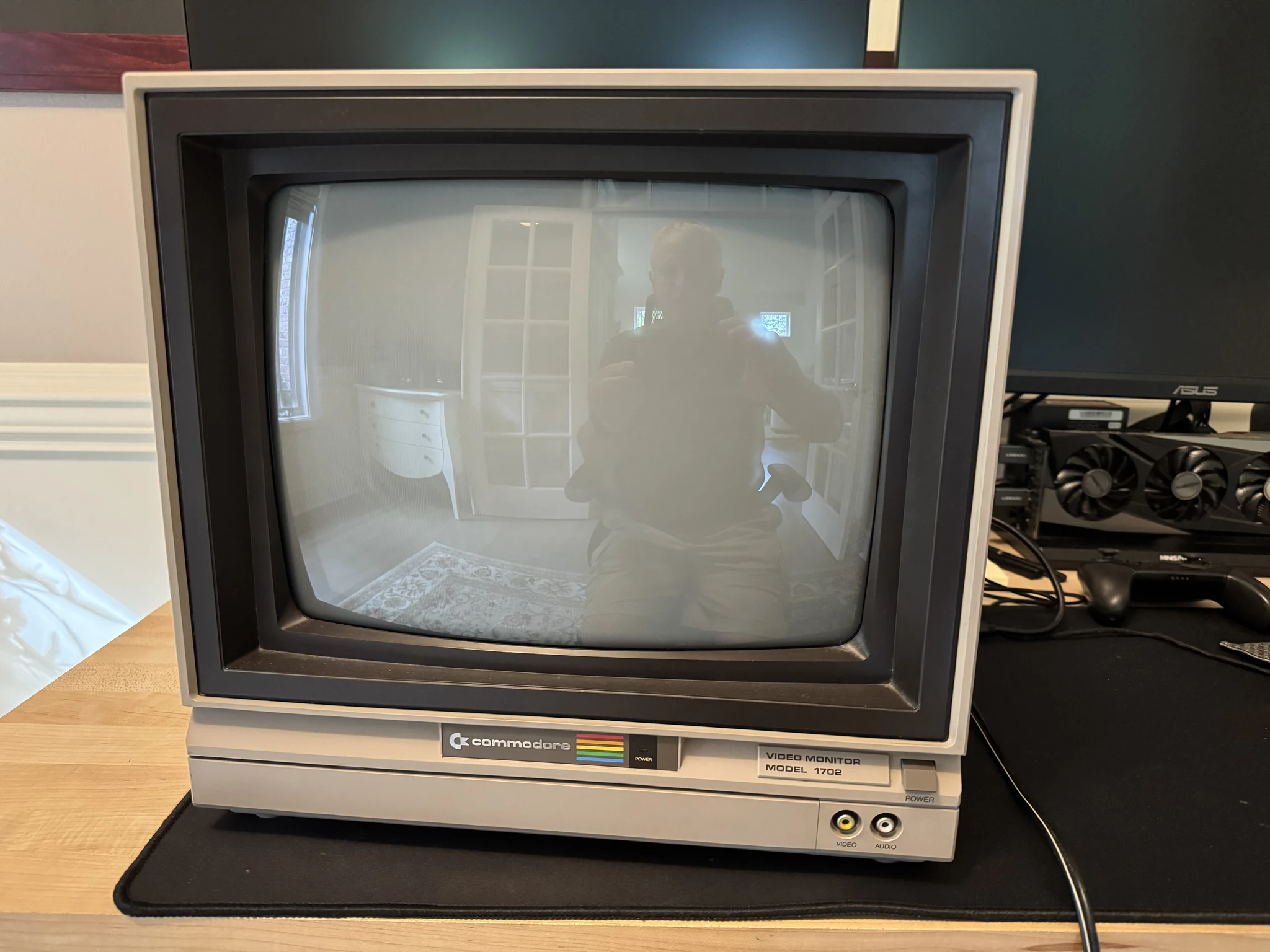
There is also very little yellowing of the plastic. The old plastics tend to change color where they have been exposed to heat. There are “retro brighting” techniques to attempt to remove the yellowing, but it looks like I won’t need to be doing that.
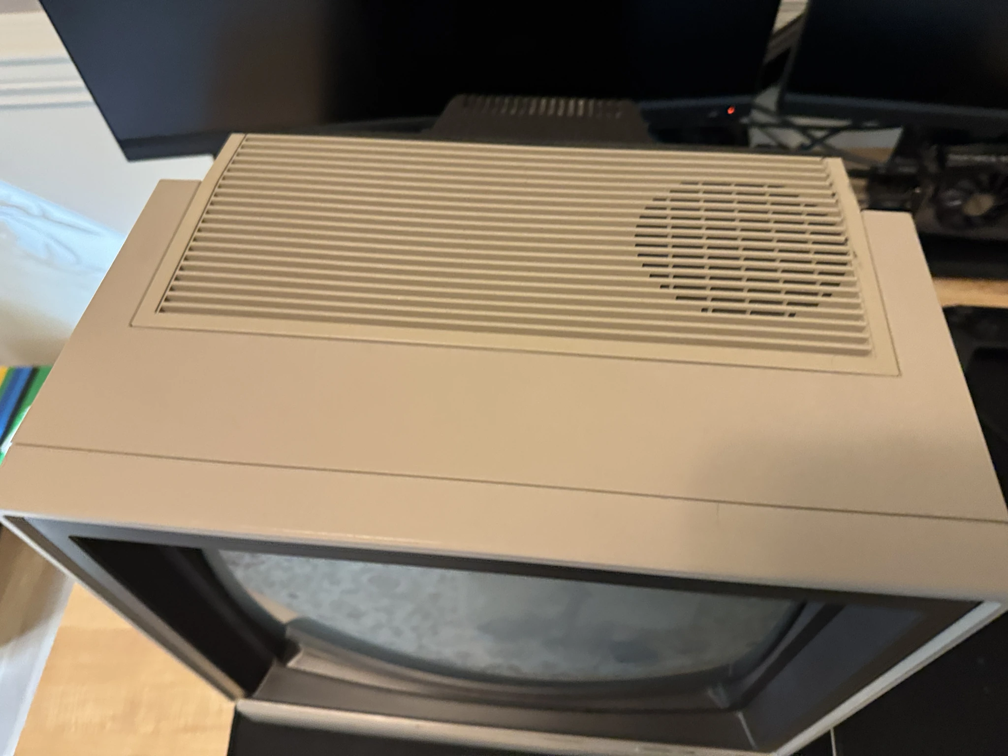
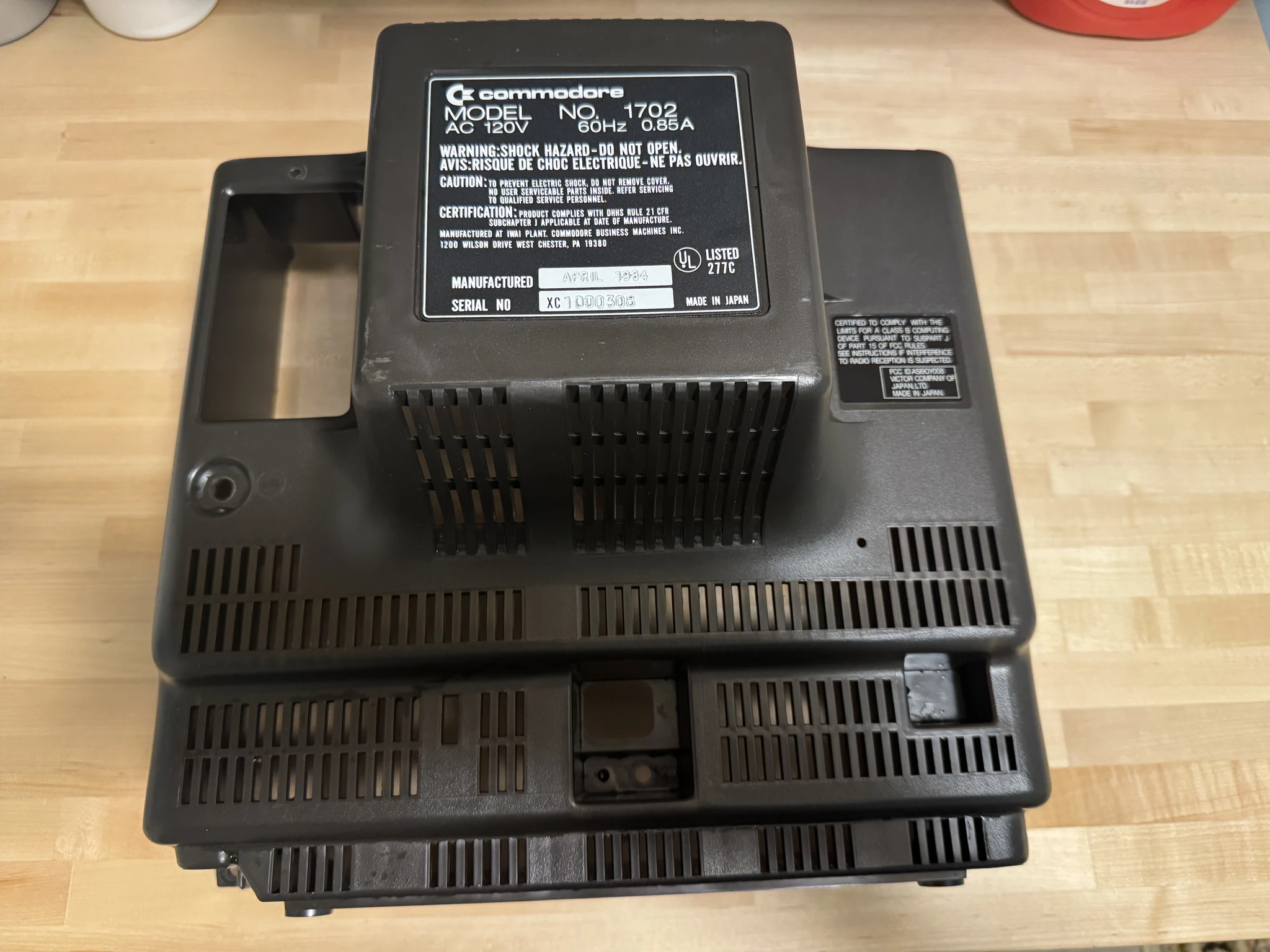
The back looks great. I’ll clean the dust off.
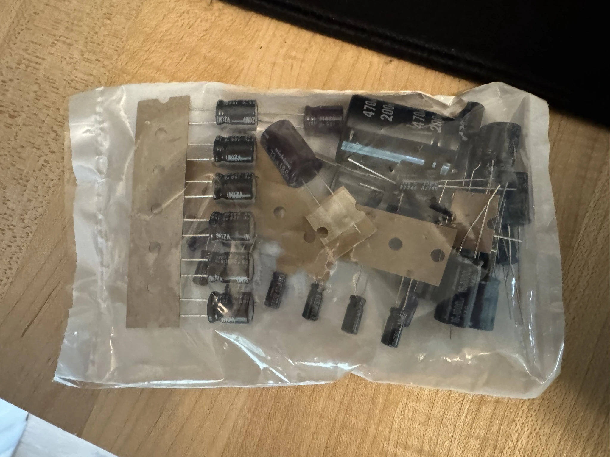
This is the Console5 capacitor kit for the 1702 monitor. This is the wiki page of instructions for this kit.
My intent is to replace all of the capacitors as the original ones could have dried up and become less effective.
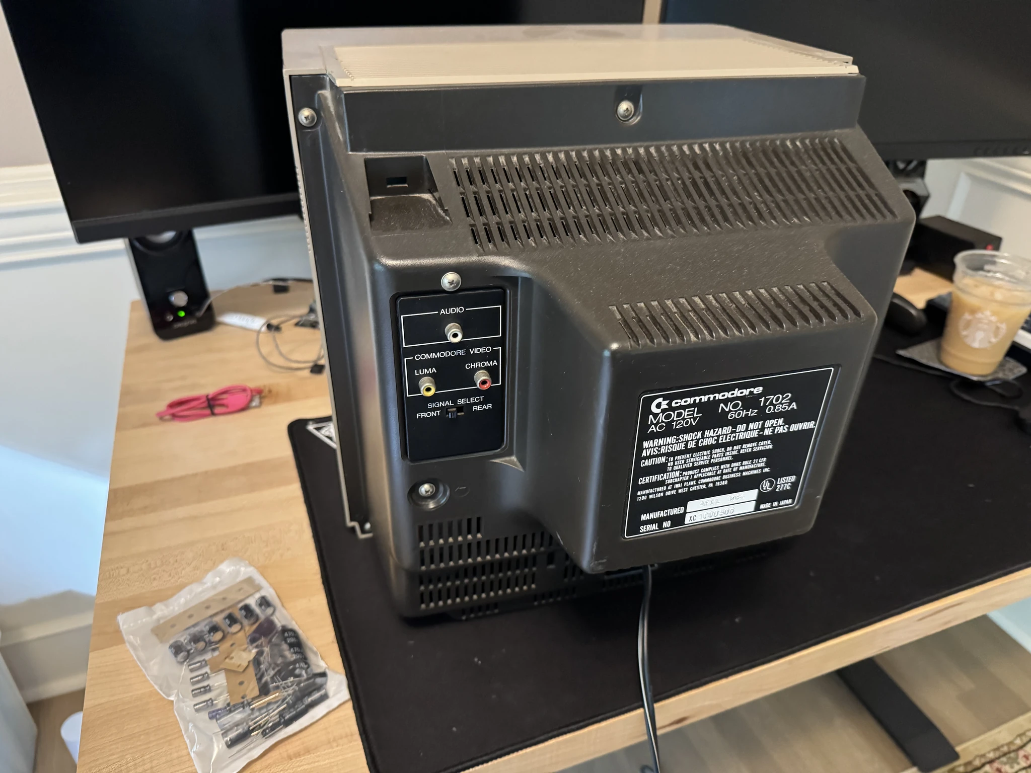
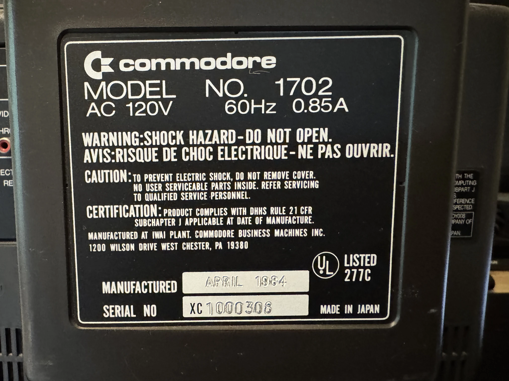
The label on the back indicates that the monitor was built in 1984. It also warns about the potential shock hazard of working on the monitor. I’m comfortable working on this as I’ve researched it thoroughly and have done this once before. This video was particularly helpful as it fully details the process and I’m grateful to the person that created and posted the video.
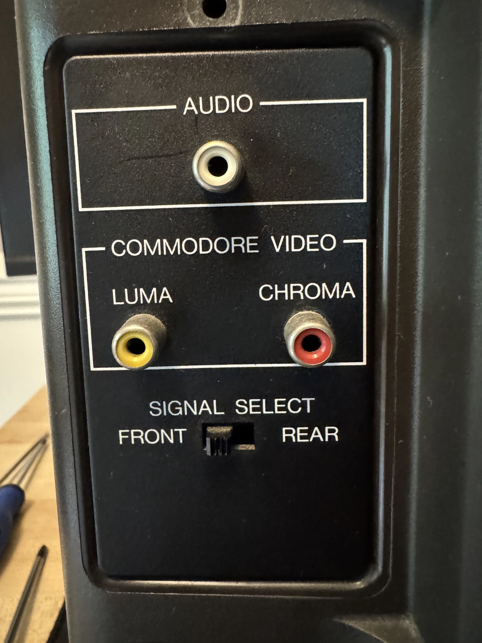
The back of the monitor has RC jacks for input and a switch to use the RC jacks on the front of the monitor. I found that my composite cable works on the front of the cable but not with the connectors on the back which expects a separate luma and chroma signals.
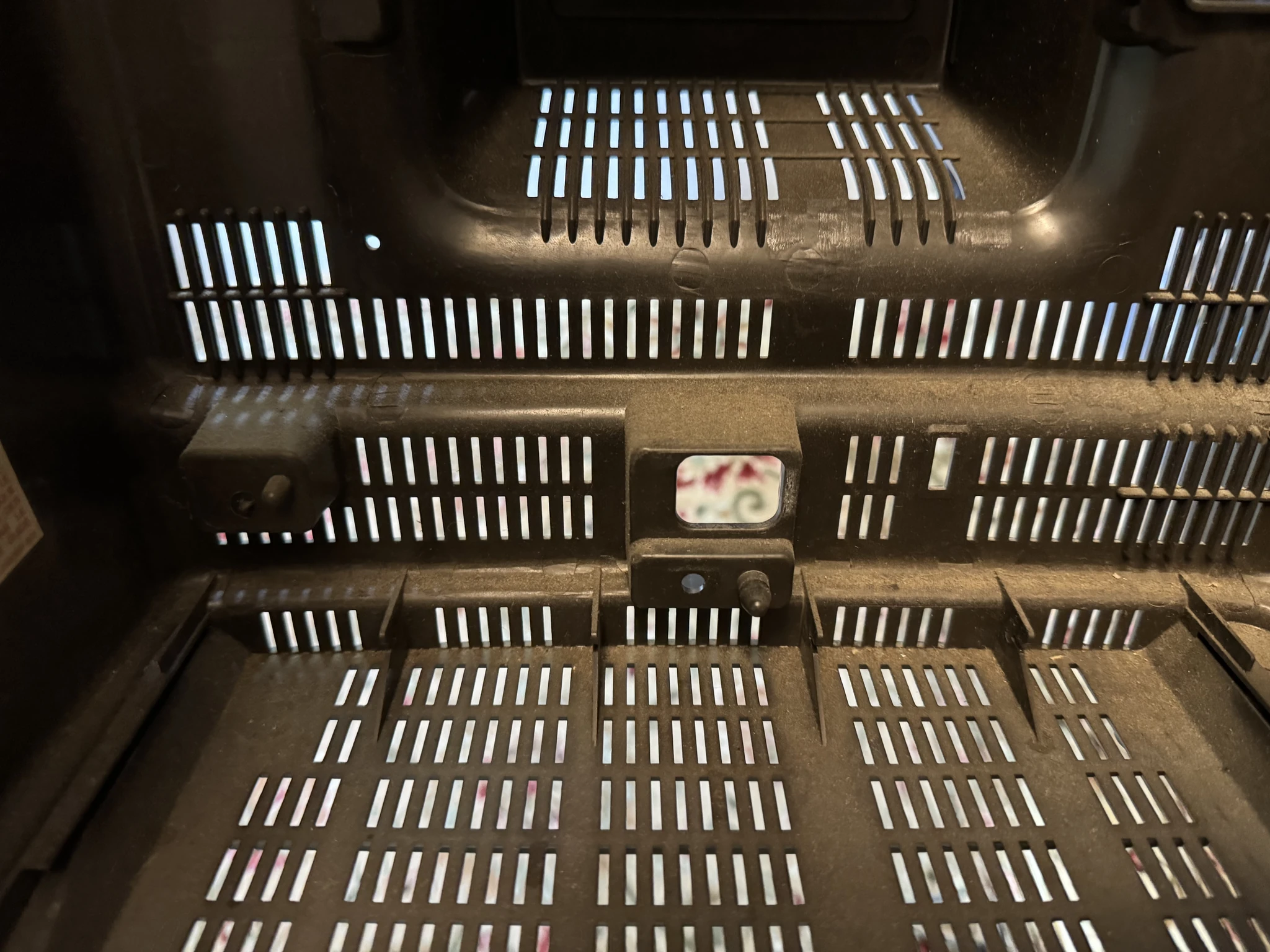
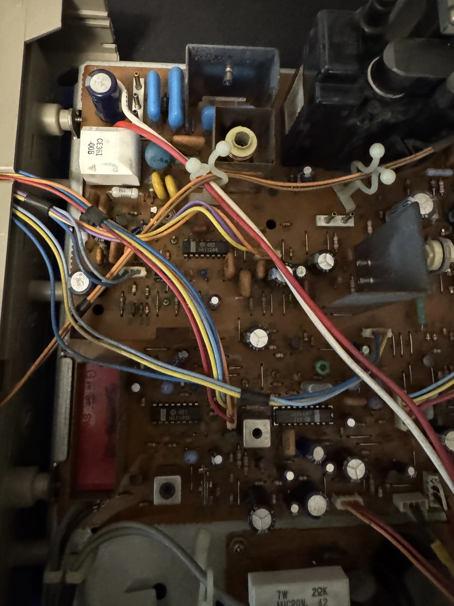
I take the back panel off. The inside is dusty and needs to be cleaned.
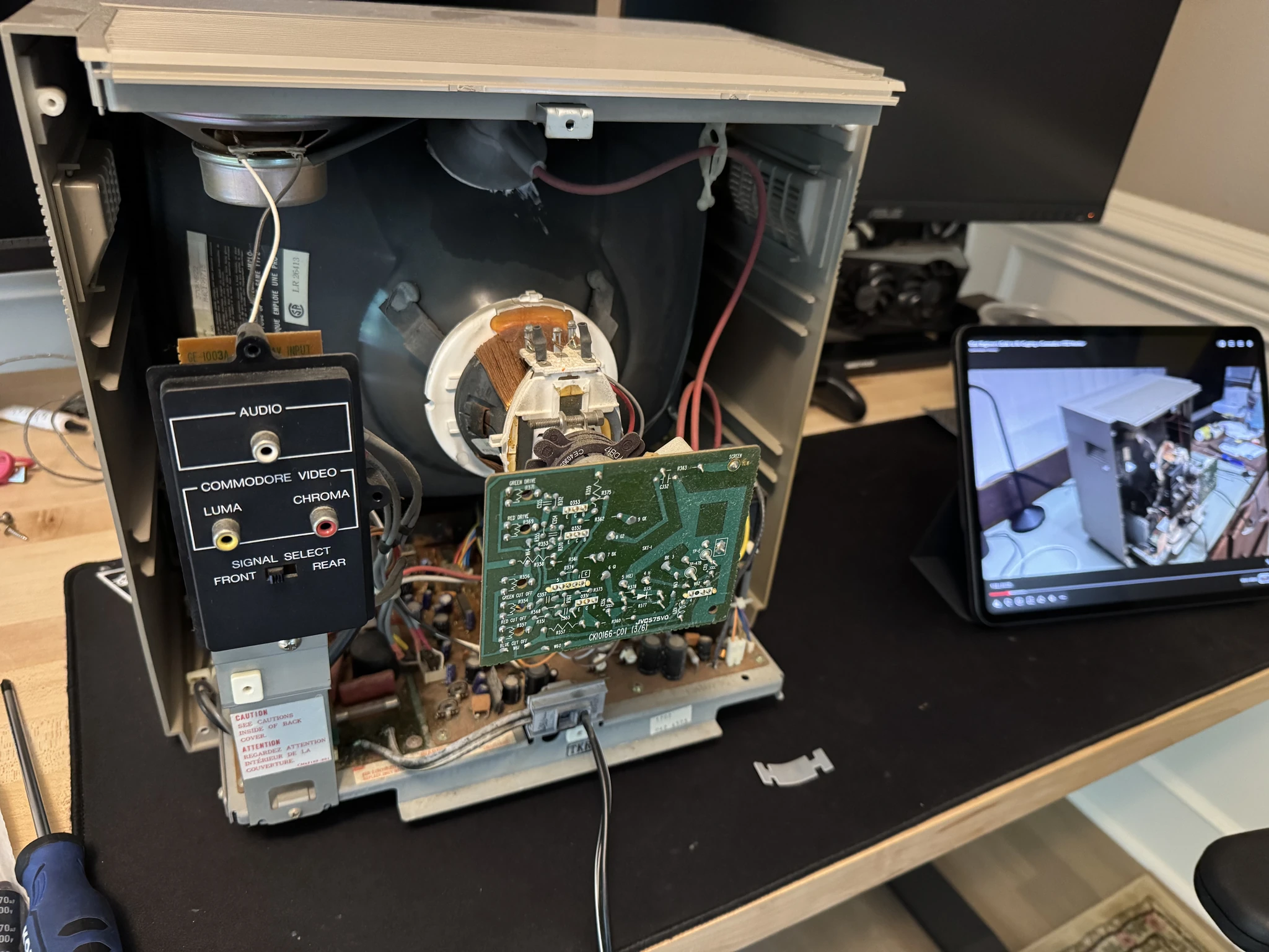
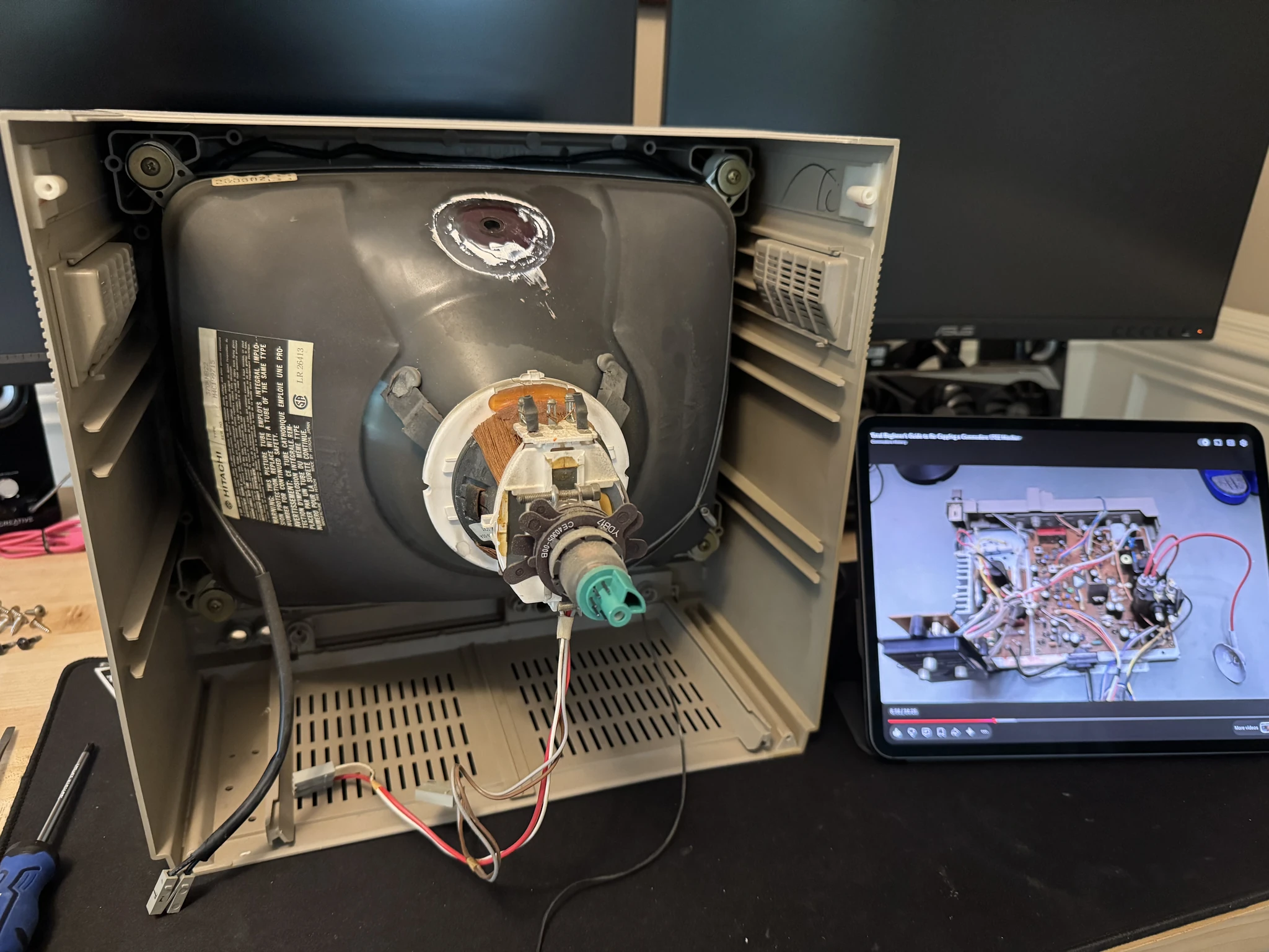
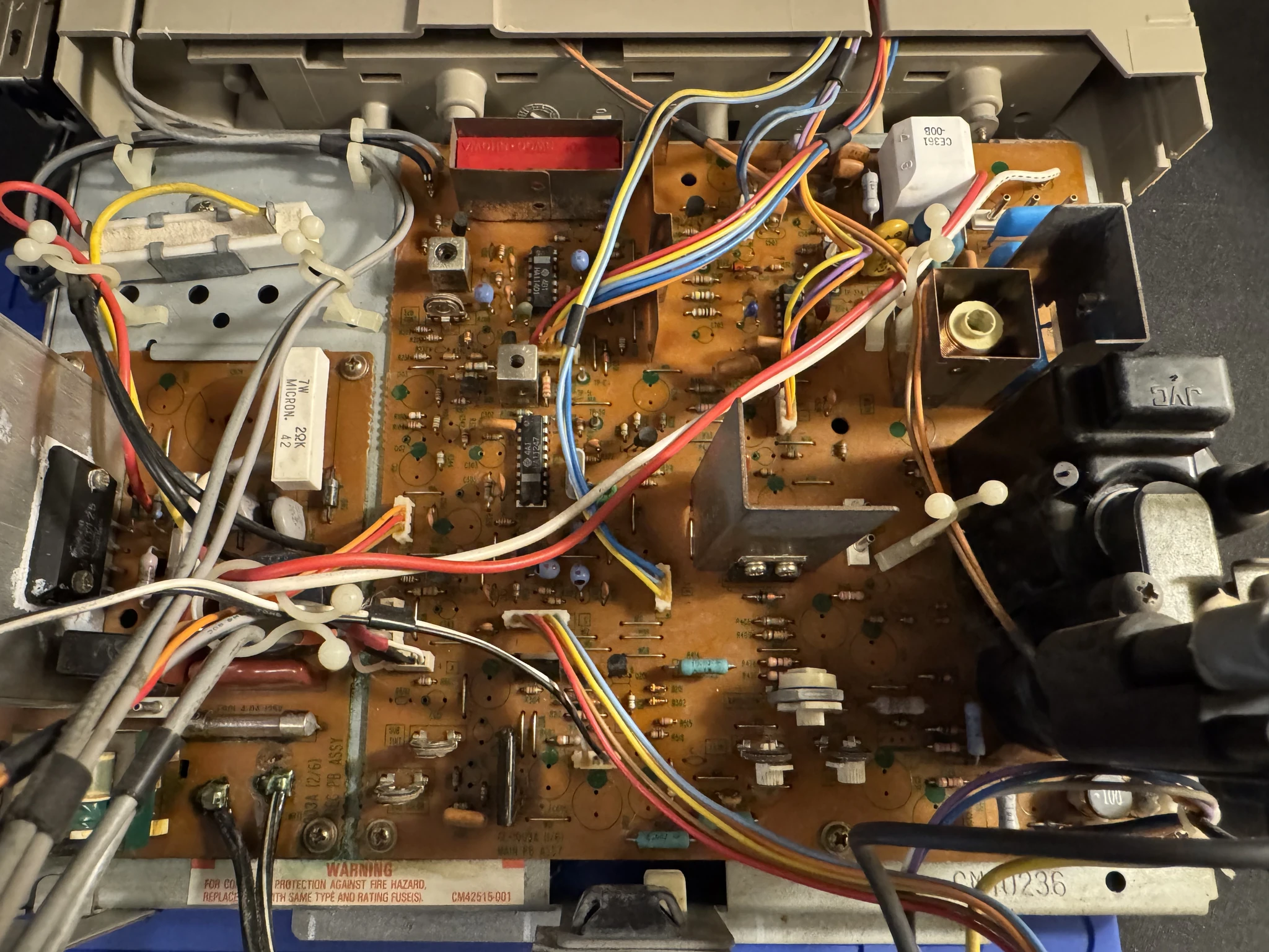
This is the inside of the monitor. I’ve got my iPad to the right to rewatch the video mentioned above and follow along as I perform the recapping steps.
There are three screws in the front that need to be removed to allow pulling out the circuit board.
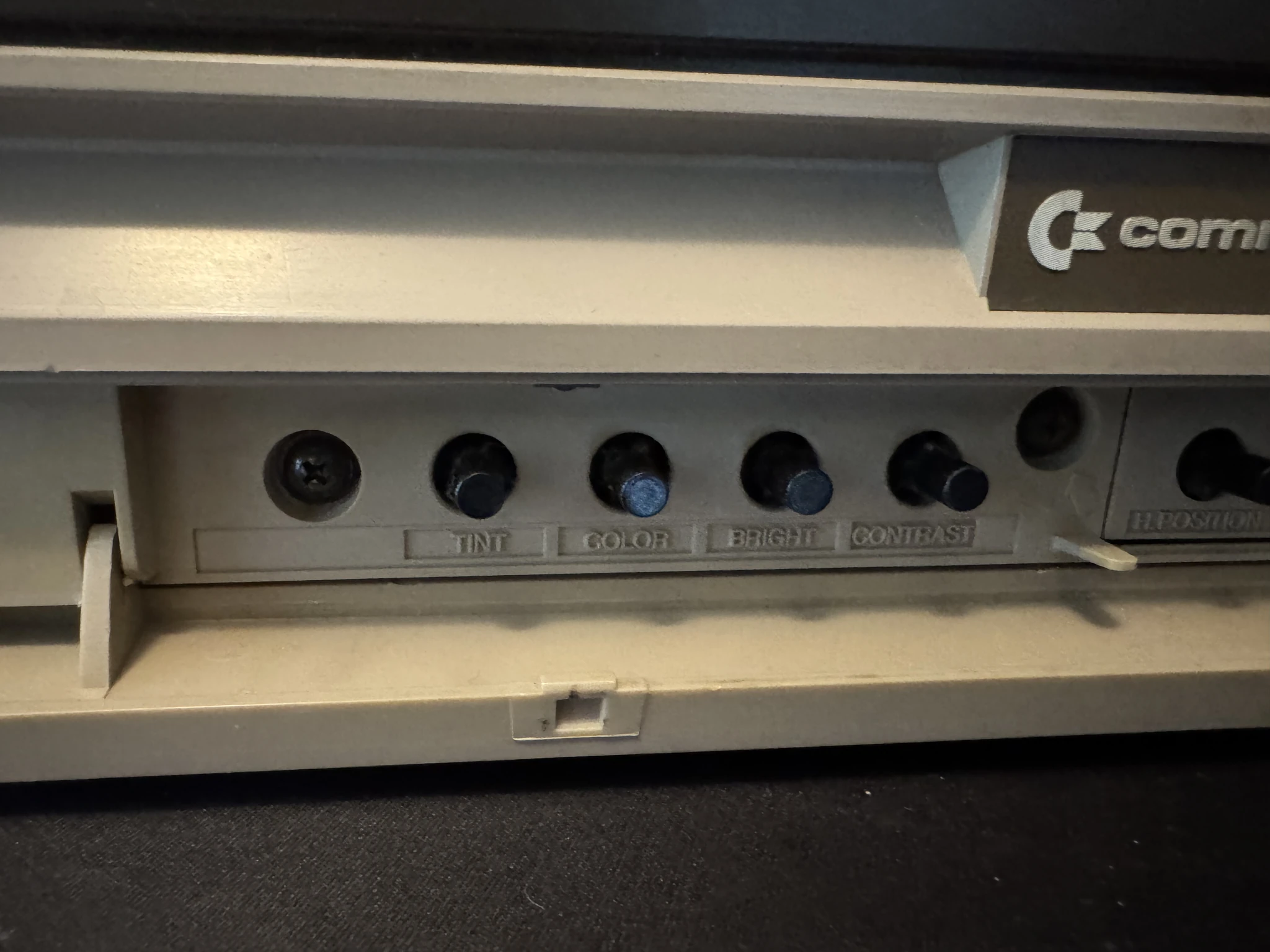
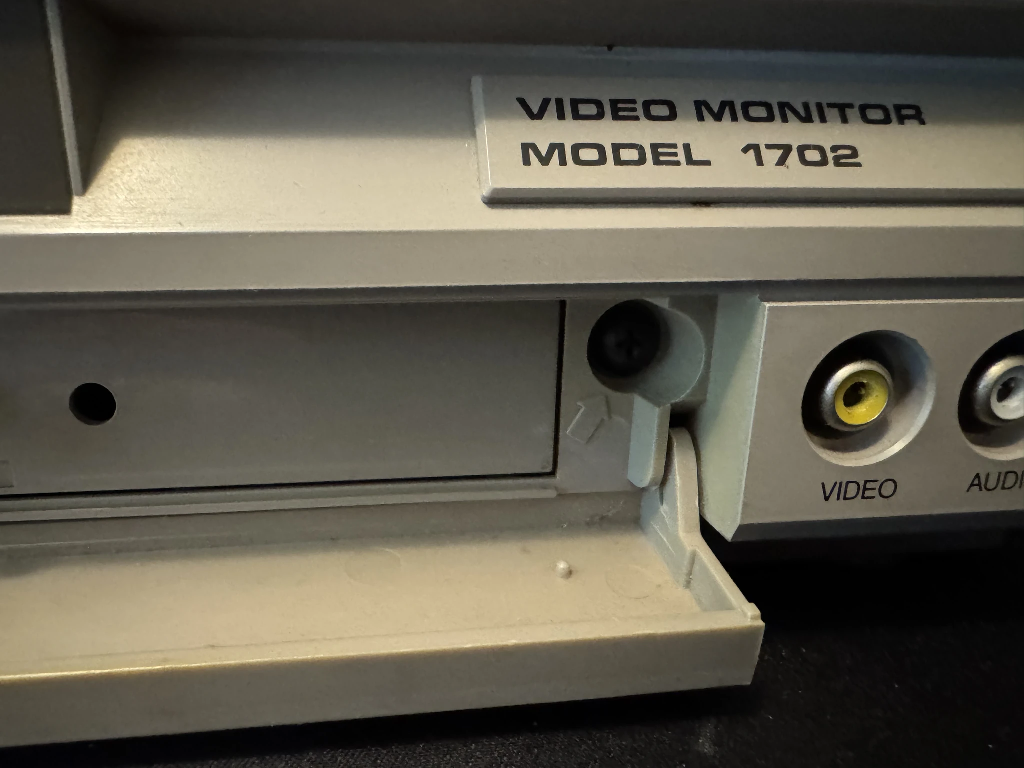
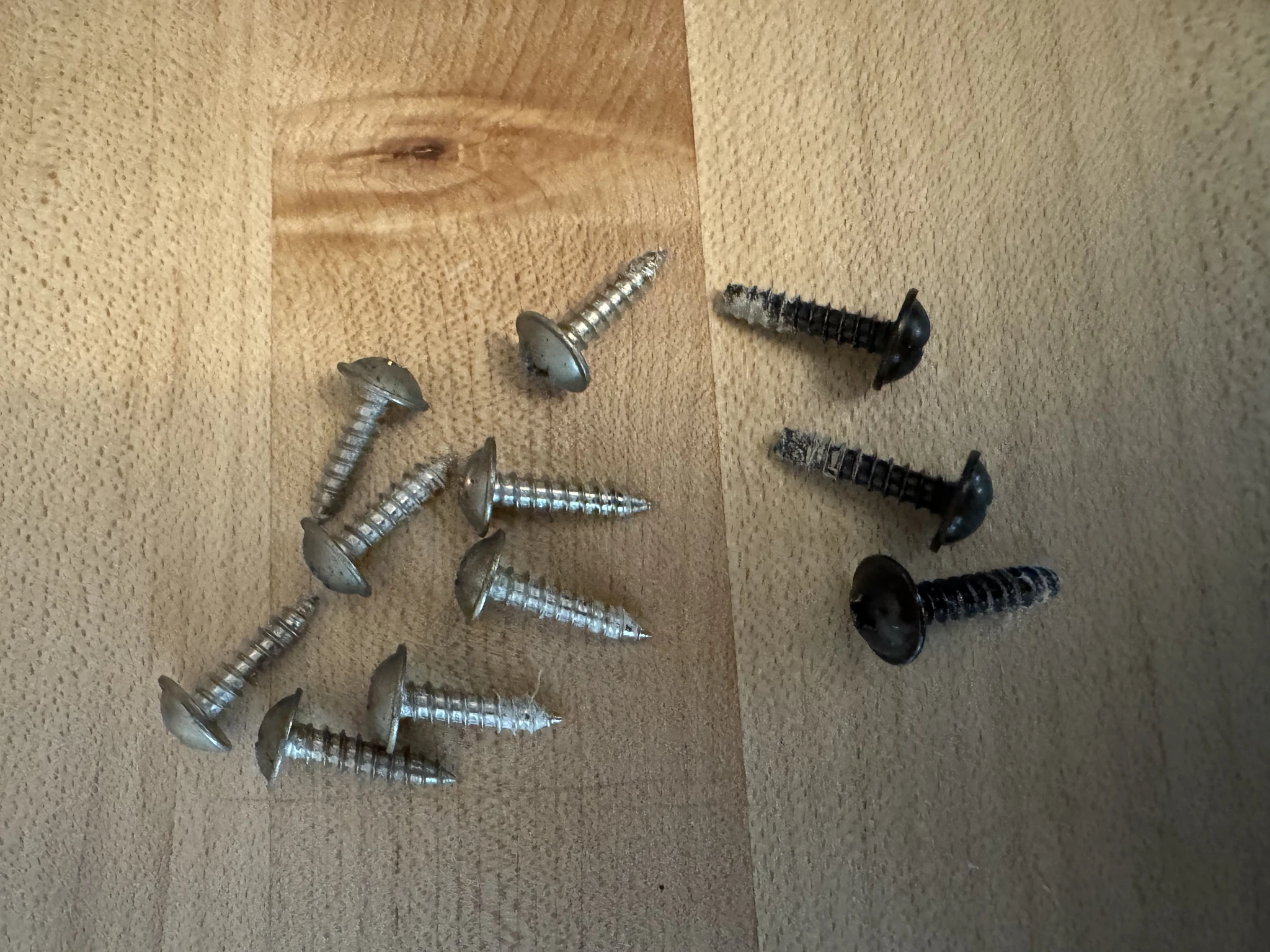
I set asside the screws for the front and back case.
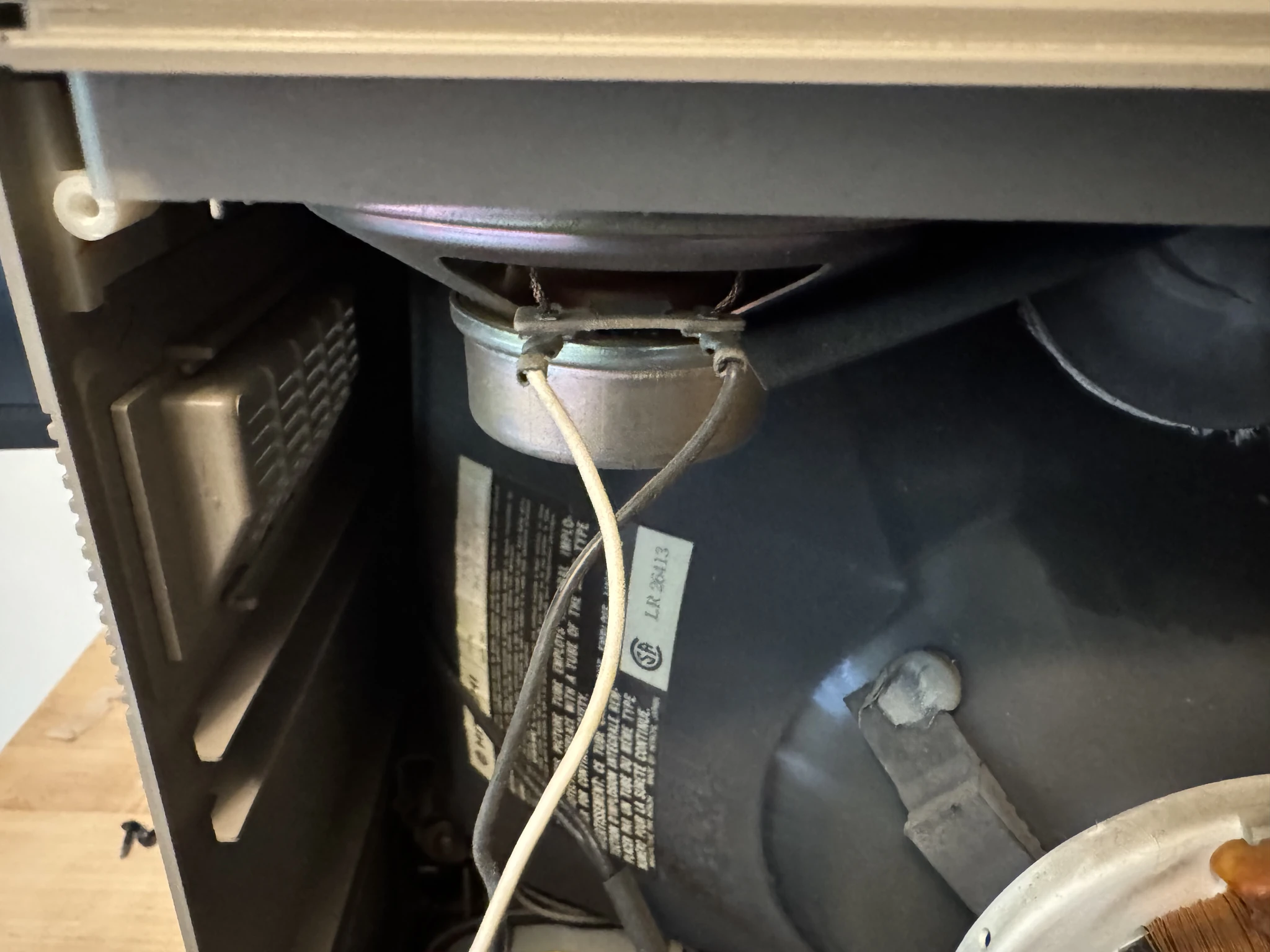
The speaker wires are disconnected and the anode wire freed so the speaker grill can be removed.
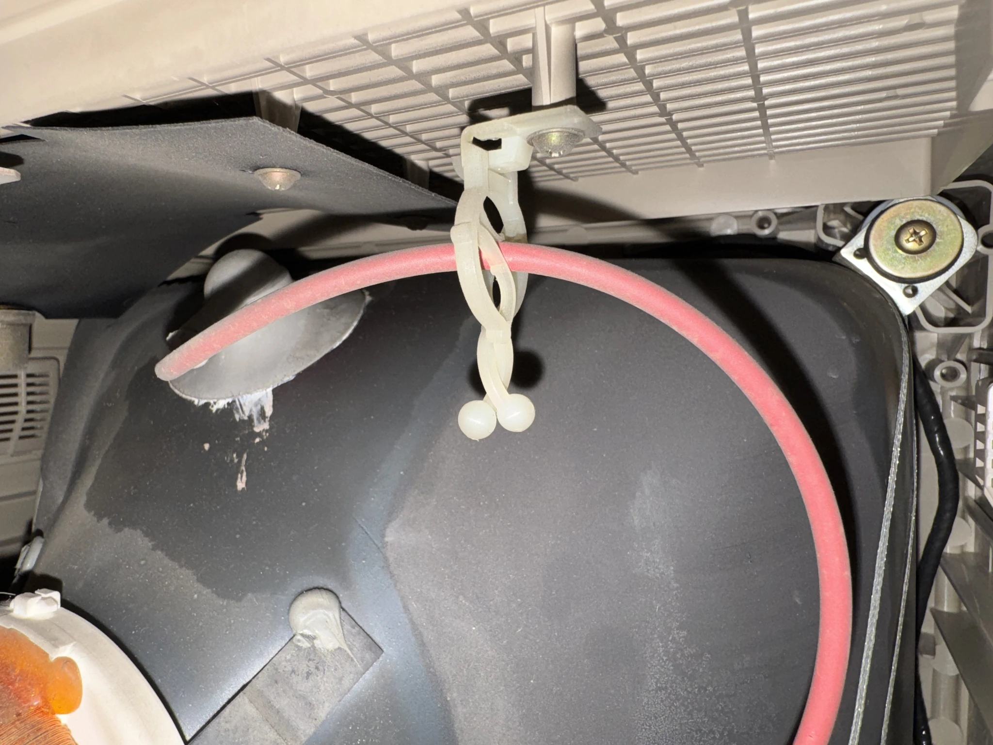
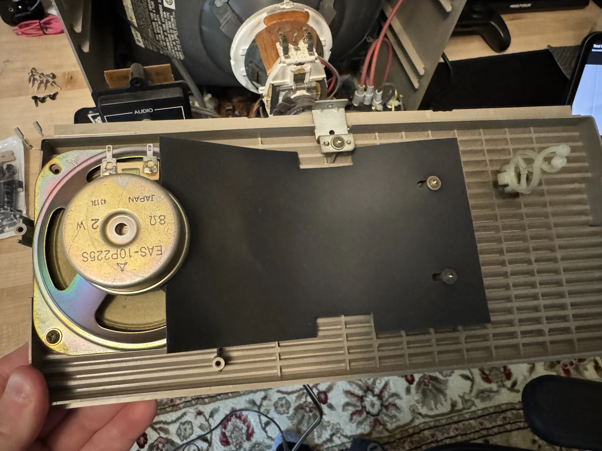
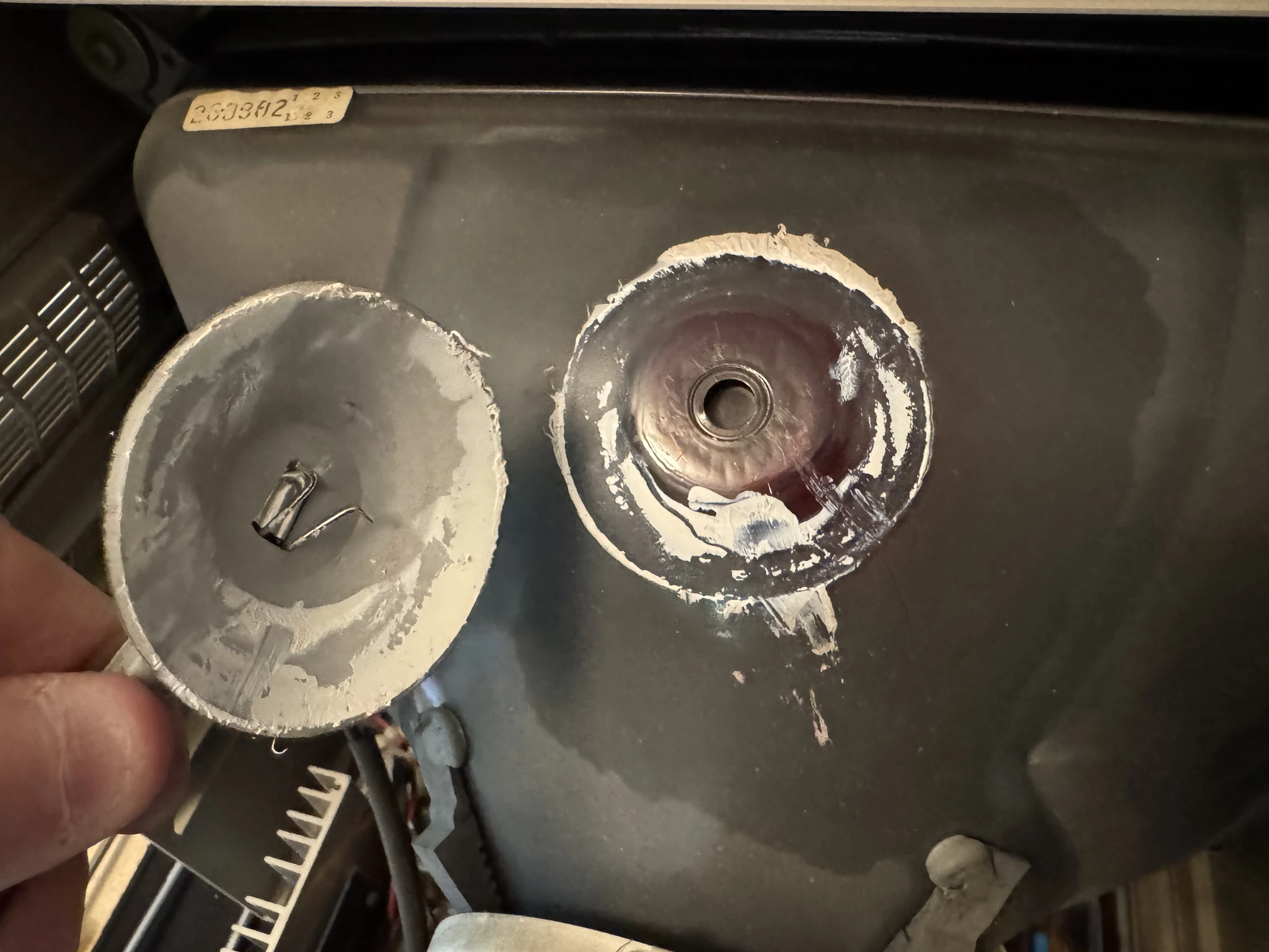
Not pictured, but before I touched the anode suction cup or anthing in this area, I followed steps to discharge the CRT (cathode ray tube). A CRT acts as a large capacitor and the worry is that if charged you could receive 1000 volts by touching the wrong part. Given that this hasn’t been turned on in years, the risk is low, however, I still follow the steps to discharge the tube. Discharging involves connecting a wire from a screwdriver to the chassis for grounding, then poking the screwdriver under the anode cup to make contact with the wire inside the anode cup to potentially hear a spark as it becomes discharged. If you are going to do this, please research this thoroughly and don’t rely on my description of how this is done. The monitor is not plugged into a power outlet while I’m working on it.
As it was, there was no spark as there was no built up charge in the CRT.
This small circuit board is removed from the yoke of the tube by gently rocking it back and forth until it comes loose and can be pulled off.
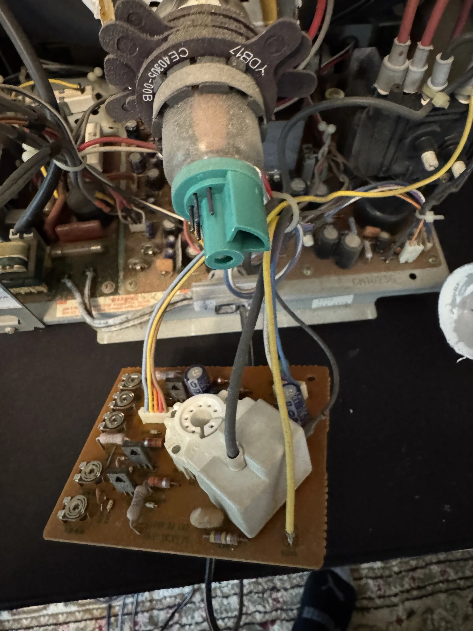
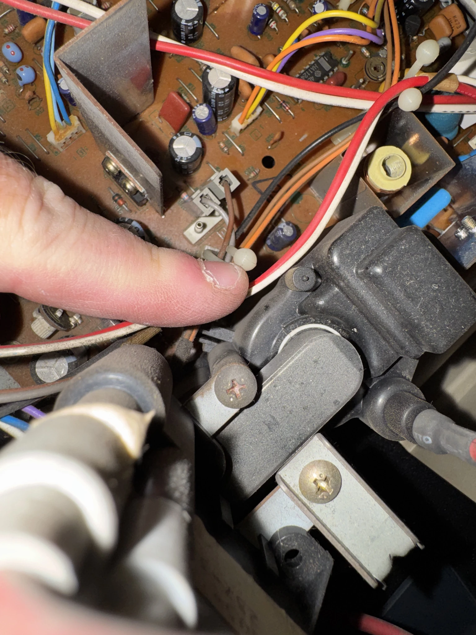
There are a few connectors that need to be removed from the board. I take photos like this so I can refer back to them if I need to when puting everything back together. In this case, I want to remember where the brown wire goes vs. where the gray wire goes.
If I miss anything, the video I’m using on YouTube has the detail I’ll need to make sure things are put back together properly.
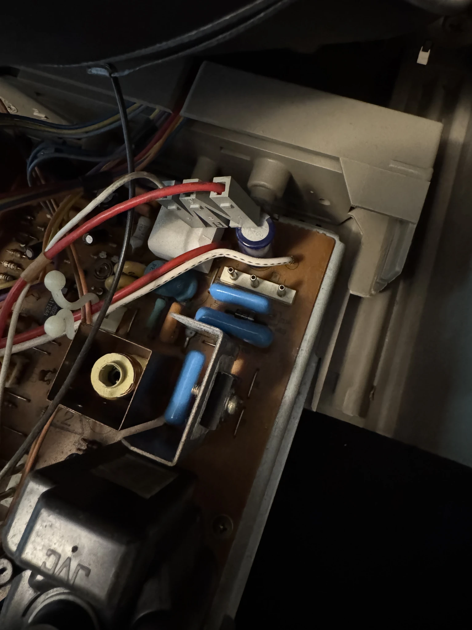
Capturing the orientation of the red and white wires. (This wasn’t really needed as the plug can only fit one way in this case.)
Yay! The main board is removed from the case.
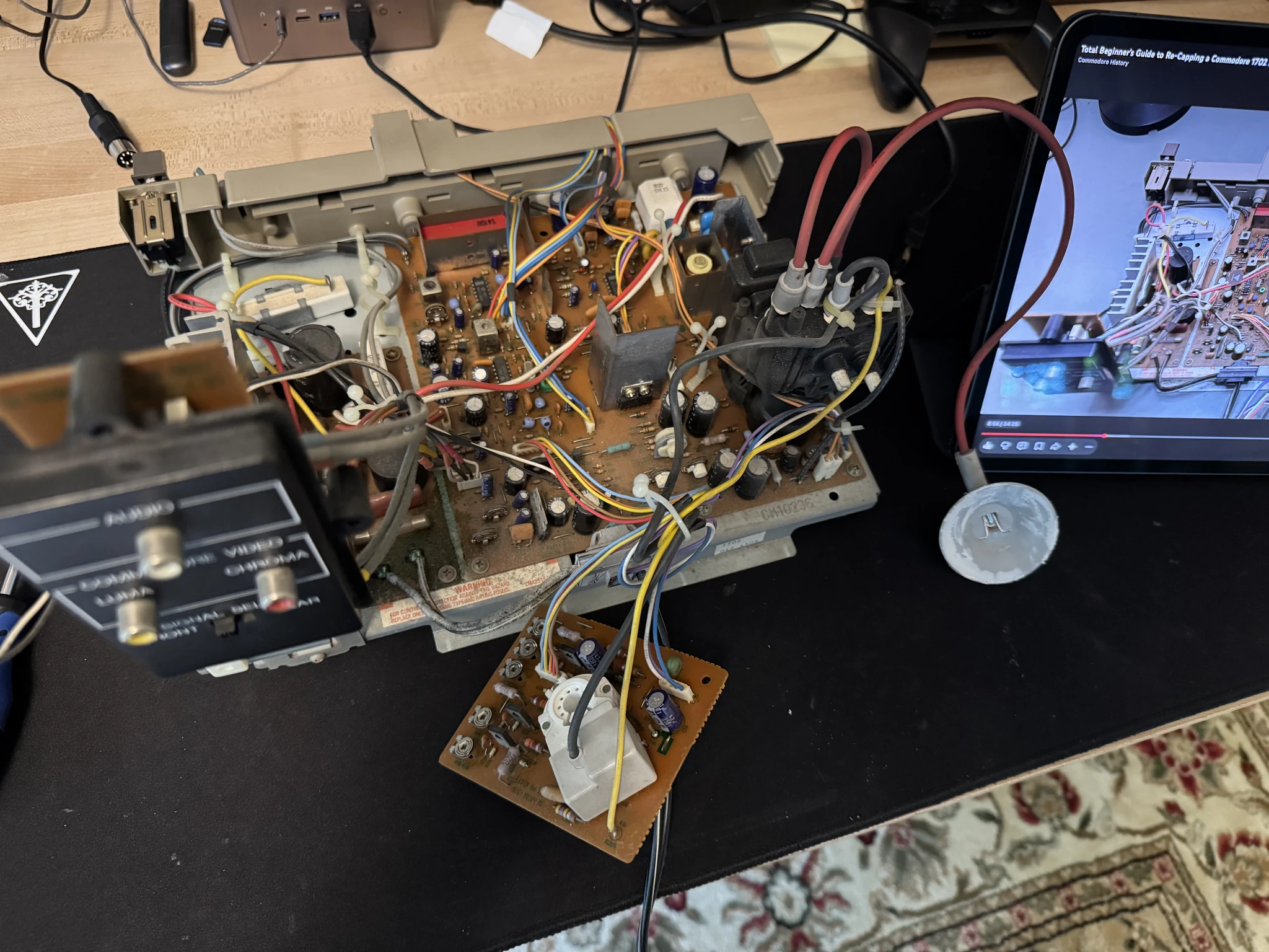
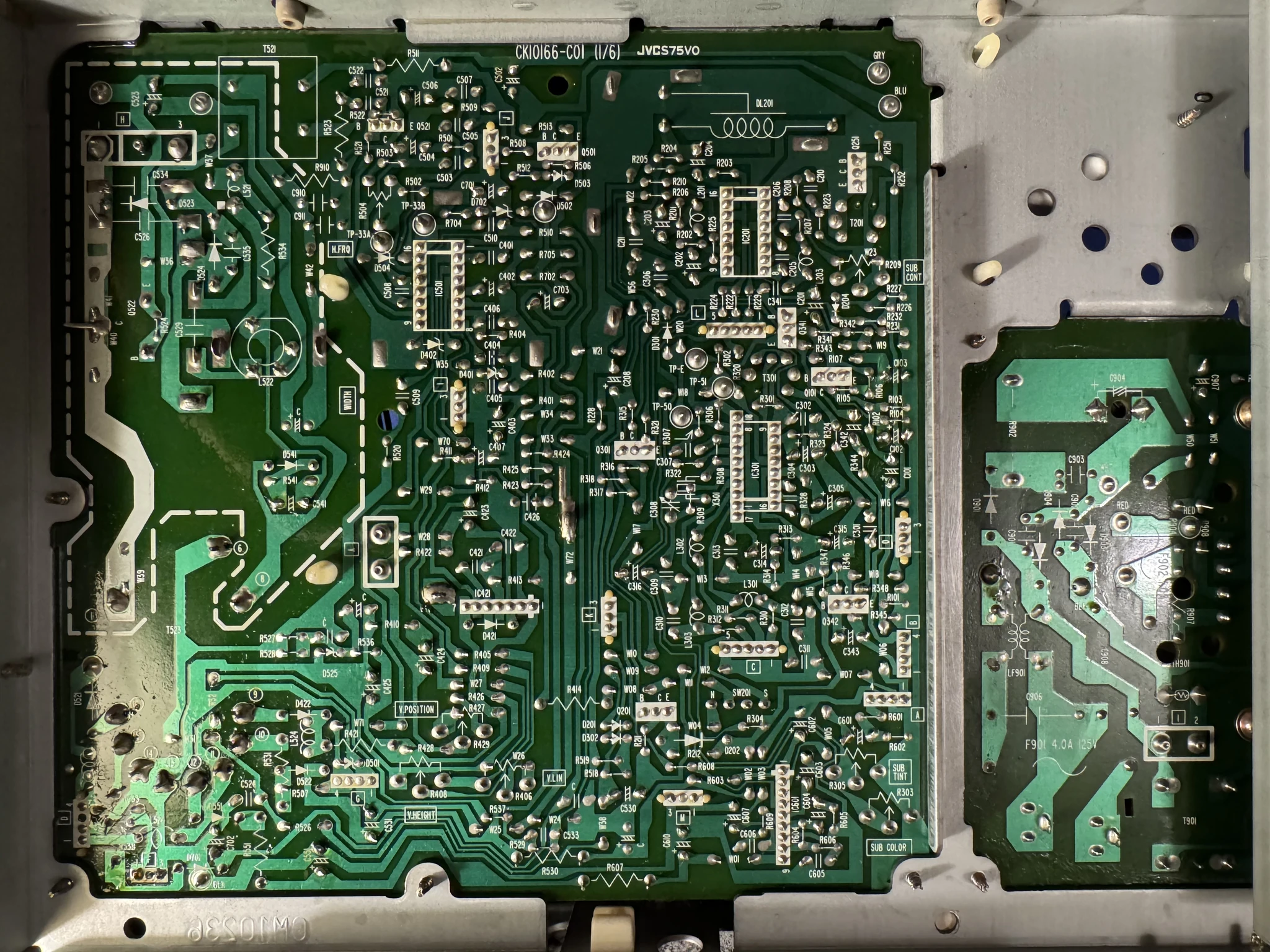
Underneath is the area I’ll be soldering on. The manufacturer did a nice job labeling everything. I don’t pretend to understand how all these components work. I only know enough about how to identify the components to remove and replace them correctly per the instructions online and on the wiki.
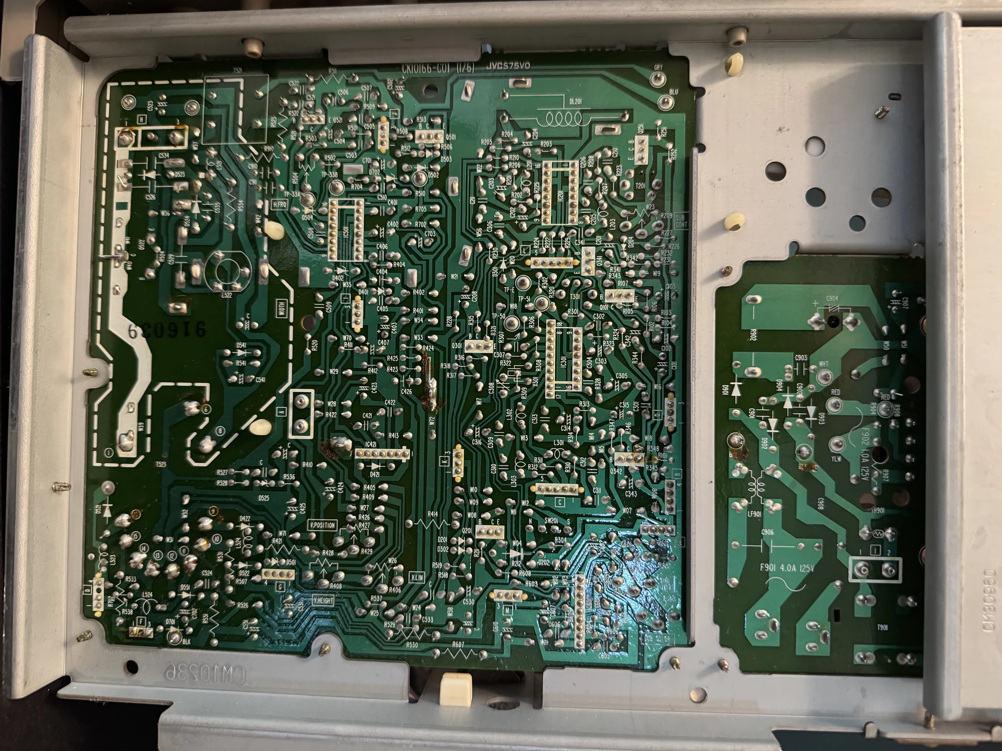
The board is a dusty mess; it is 42 years old after all. I’ll want to clean it. It isn’t absolutely necessary to clean it but it will make me feel good knowing that the inside of the monitor is spiffy clean.
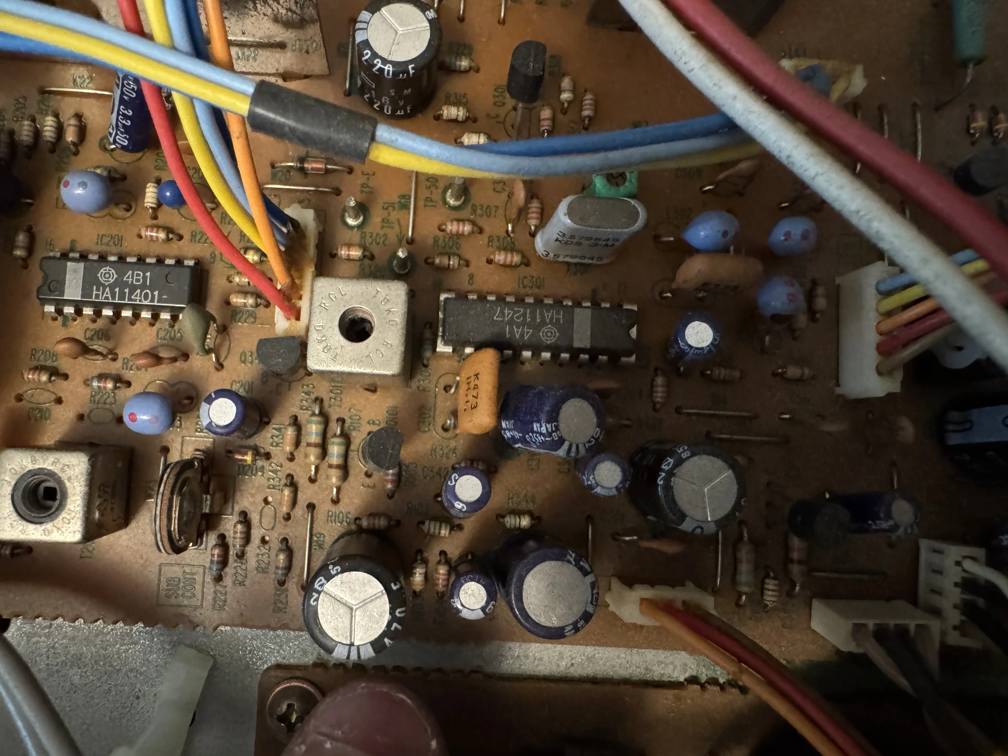
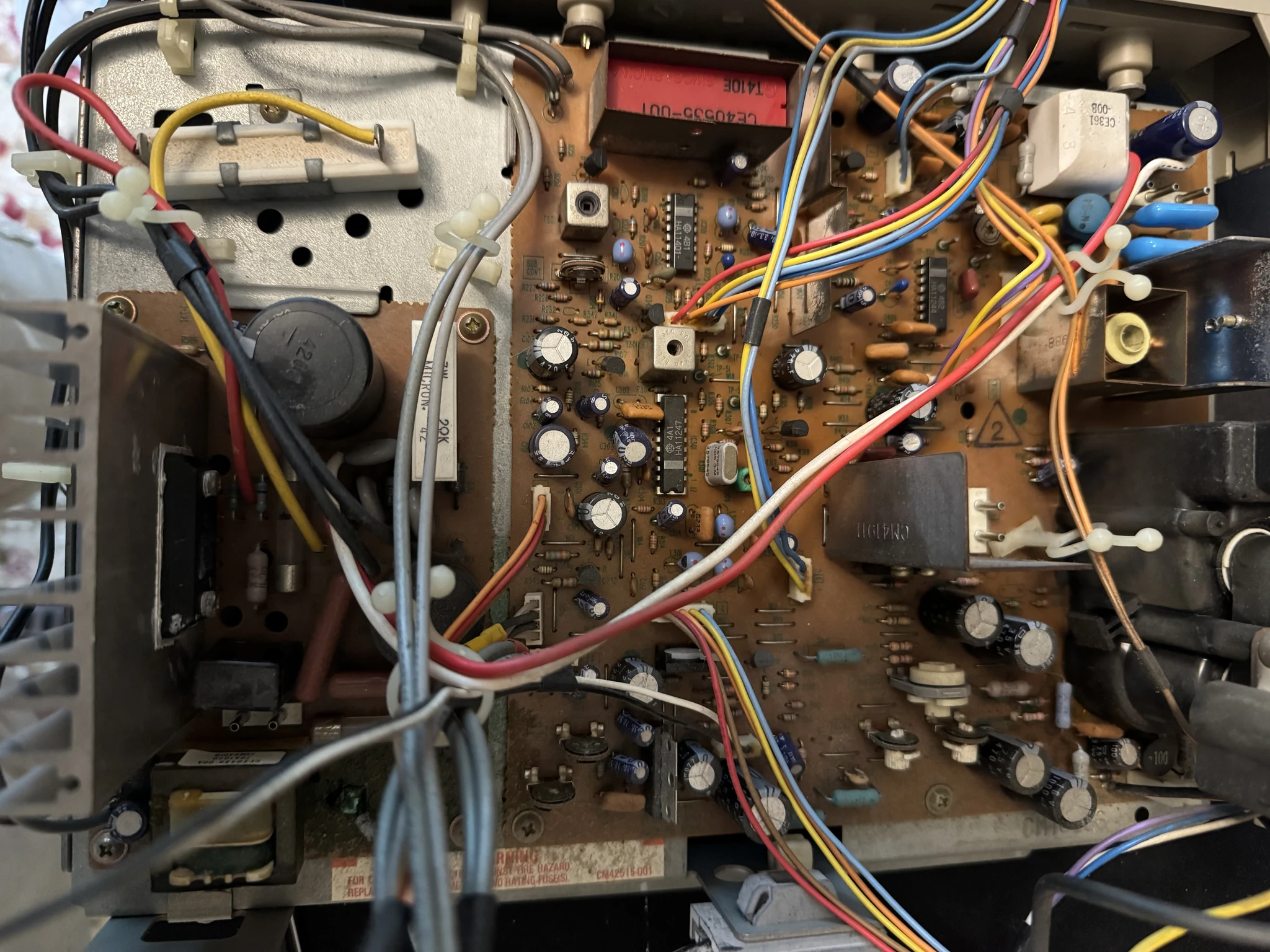
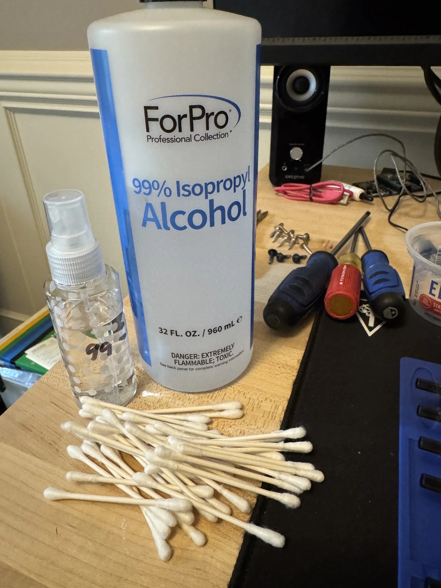
Weapons of choice are Q-tips and isopropal alcohol. The video waited to do this step after the old capacitors are removed. That makes more sense and I end up cleaning it again later.
An area after some cleaning.
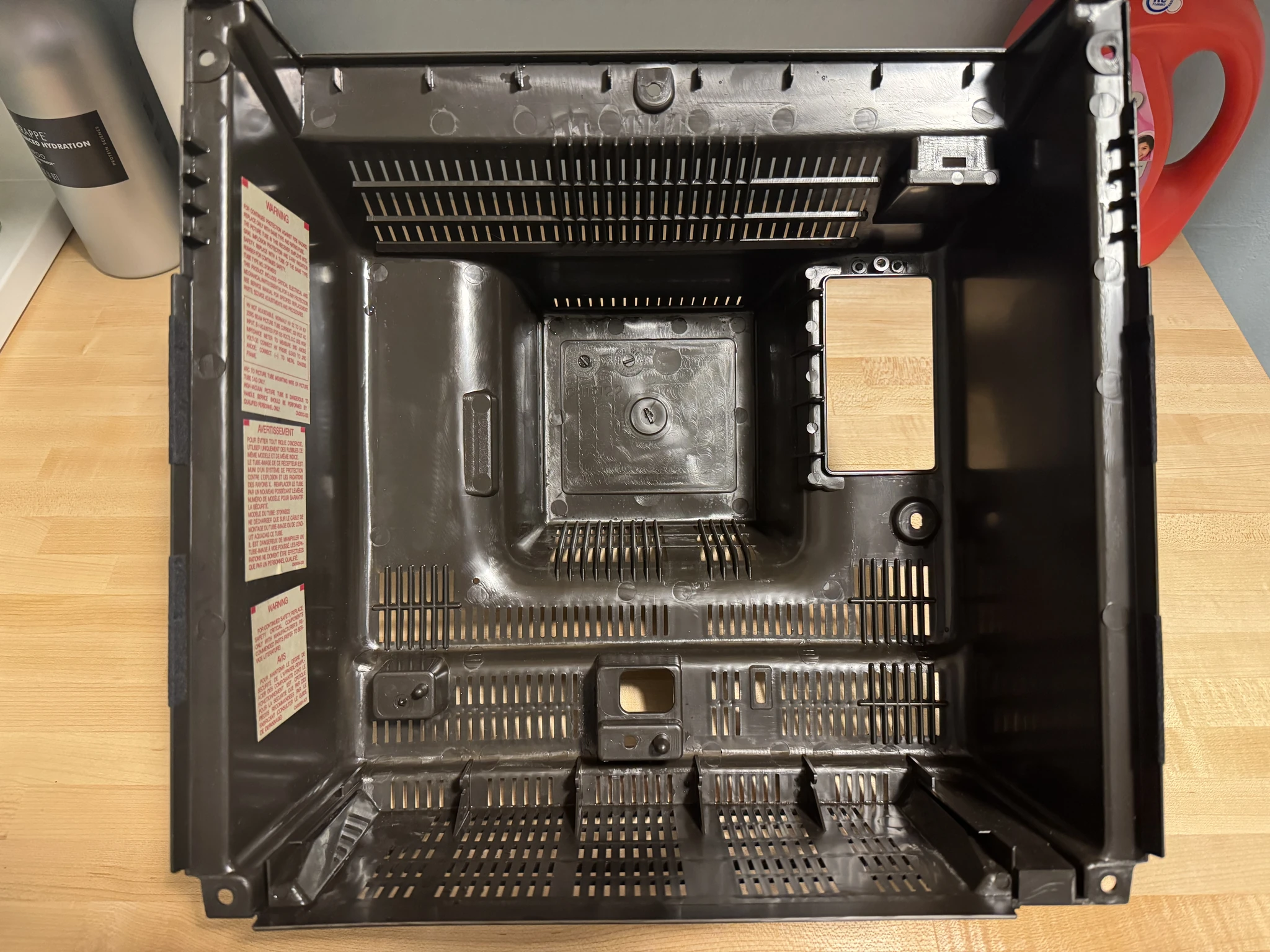
I also clean the back case with some soap and water.
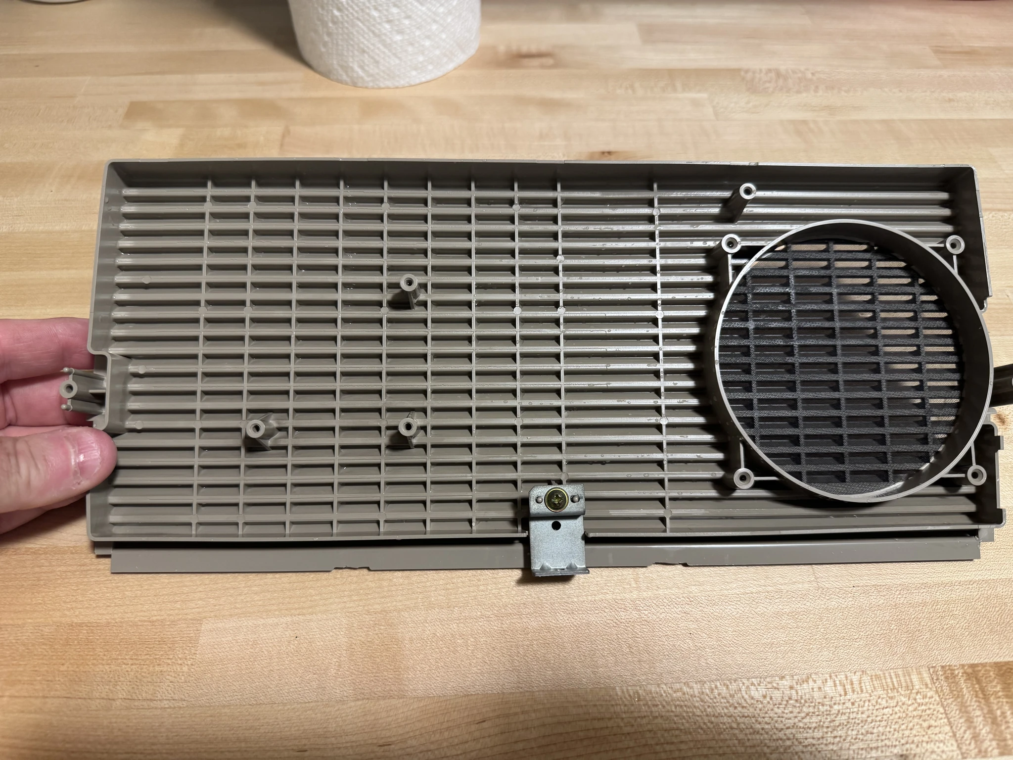
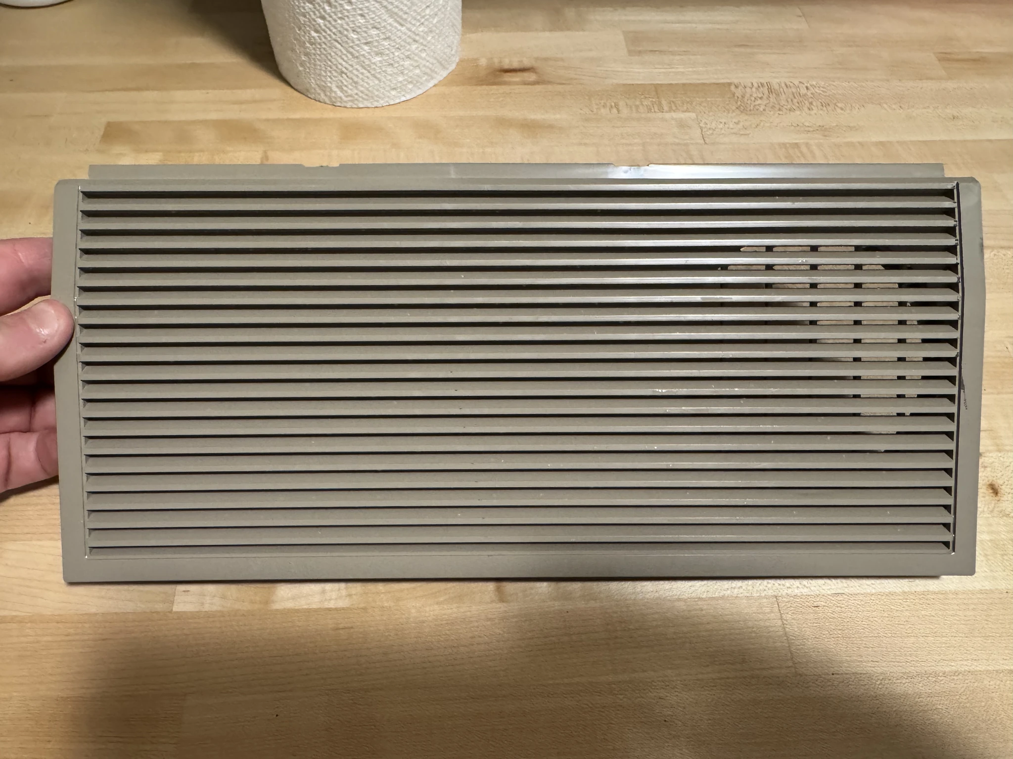
I clean the speaker grille.
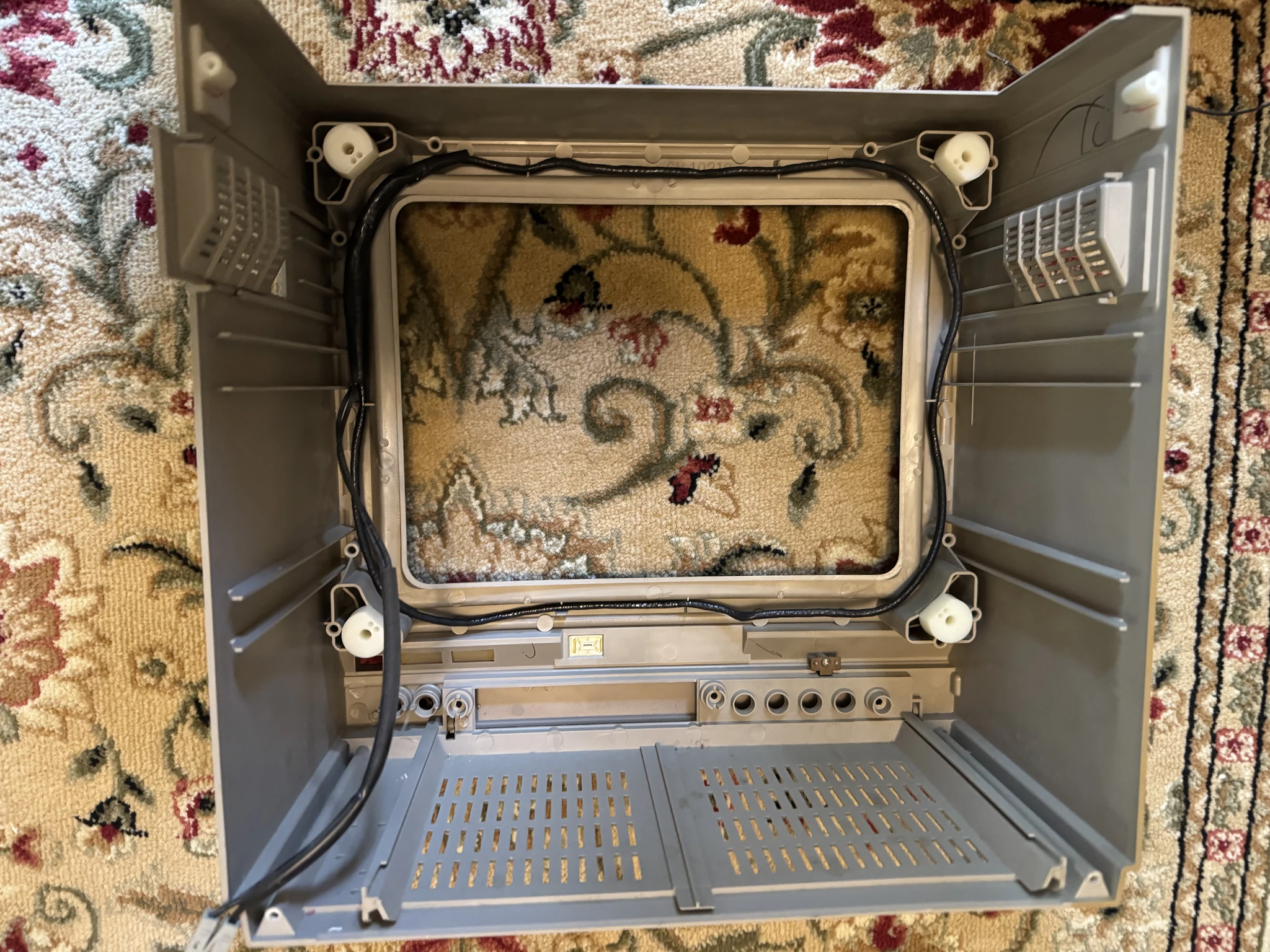
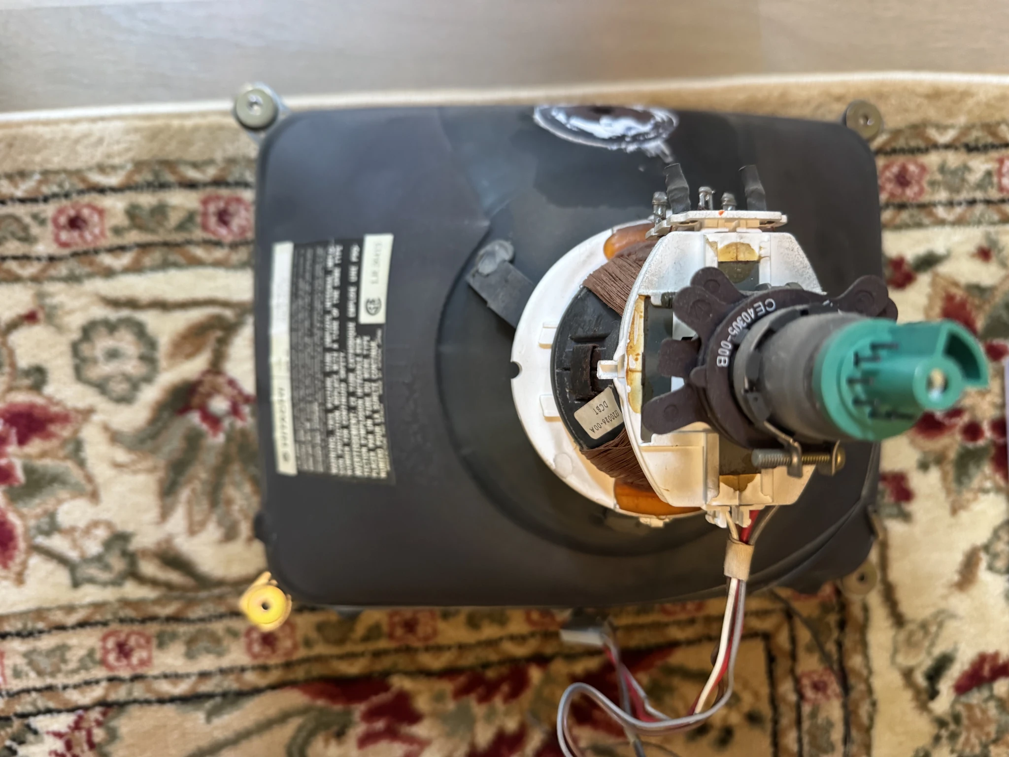
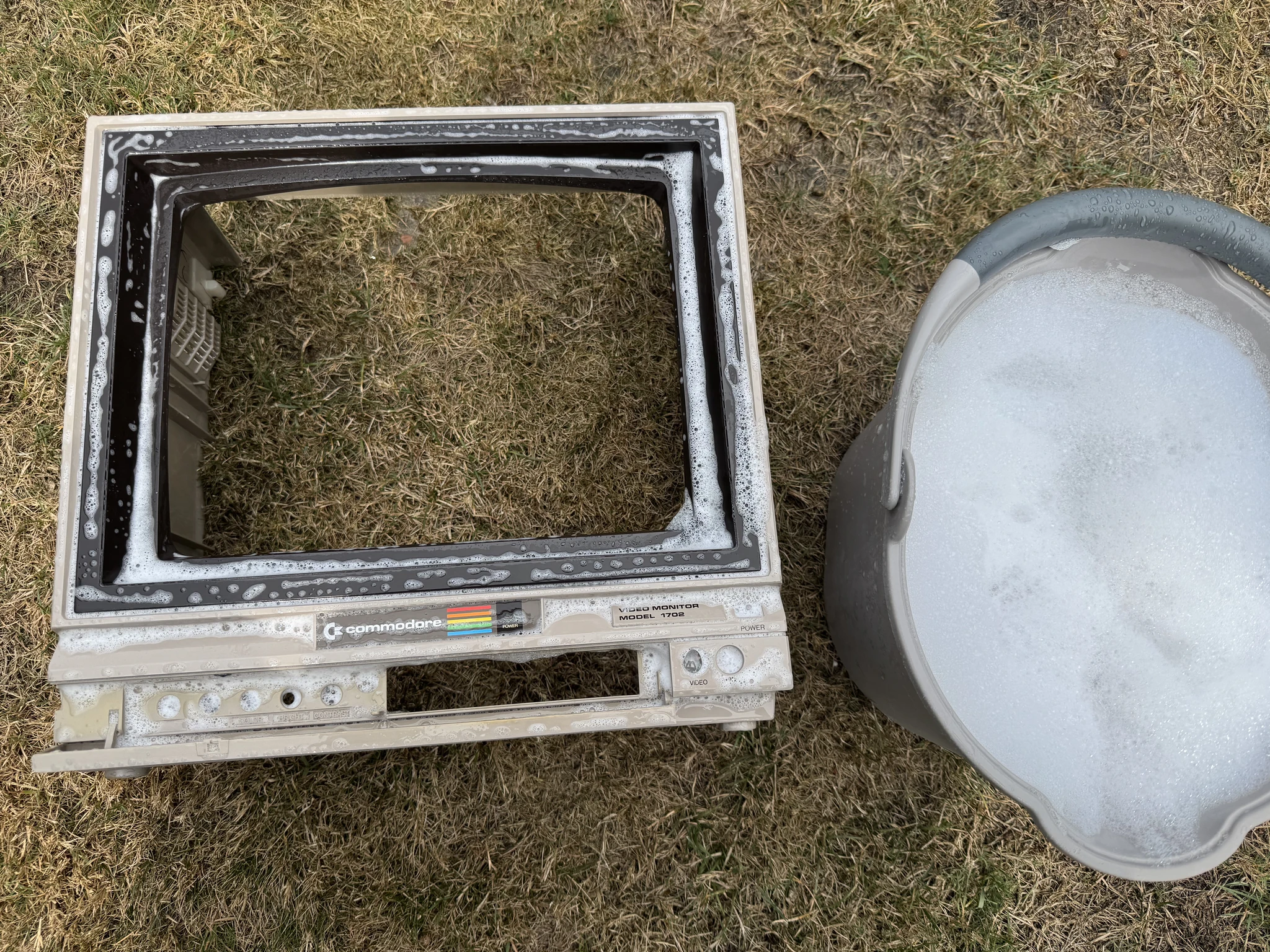
I remove the tube carefully and remove the degausing cable and wash the front case in soap and water in the backyard.
On both circuit boards I take pictures for reference of where the current capacitors are installed and what their orientation is. Most of them require being oriented correctly where the positive lead goes in the positive hole and the negative lead goes in the negative hole. The positive lead is always a little longer than the negative one. On the capacitor itself, a stripe indicates which side of the capacitor is the negative lead side. On top of that, the printed circuit board is marked. What all of that, I didn’t really need to refer to my pictures as it was easy to identify the proper orientation.
The video and wiki both reference a capacitor that is labelled incorrectly on the printed circuit board. For this one case, you want to reverse the position of the positive and negative leads rather than do what it says on the printed circuit board. I make sure to follow through on this one exception.
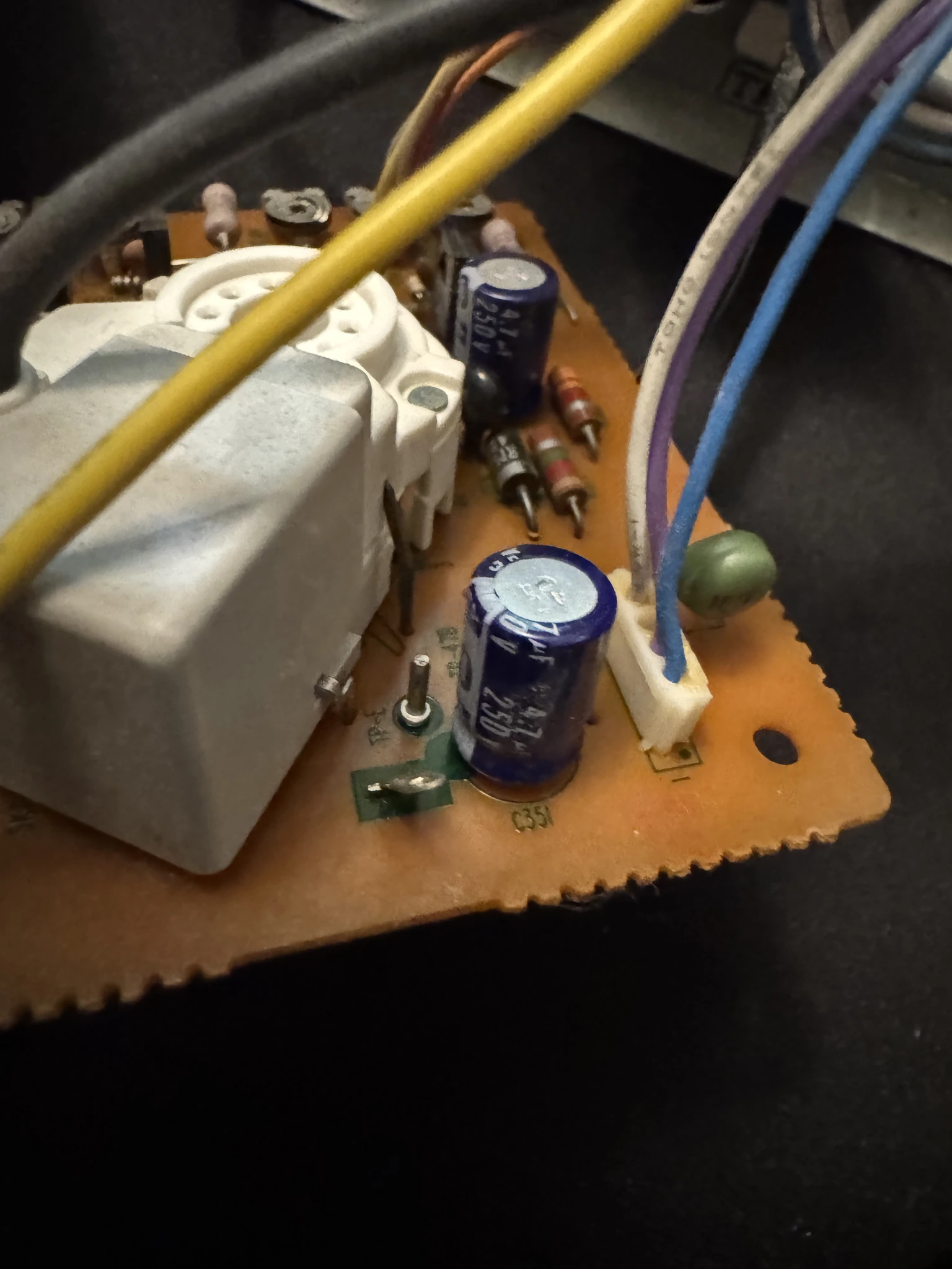
Now I remove all 41 of the capacitors. Here I remove the one at the marked position, C905, on the circuit board for the tube yoke. I have a desoldering iron which heats up the solder and sucks it up via vacuum.
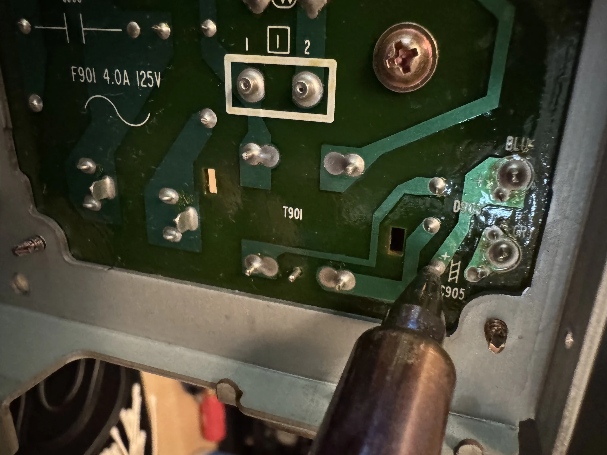
You can see that the capacitor is disconnected from the board and can be removed.
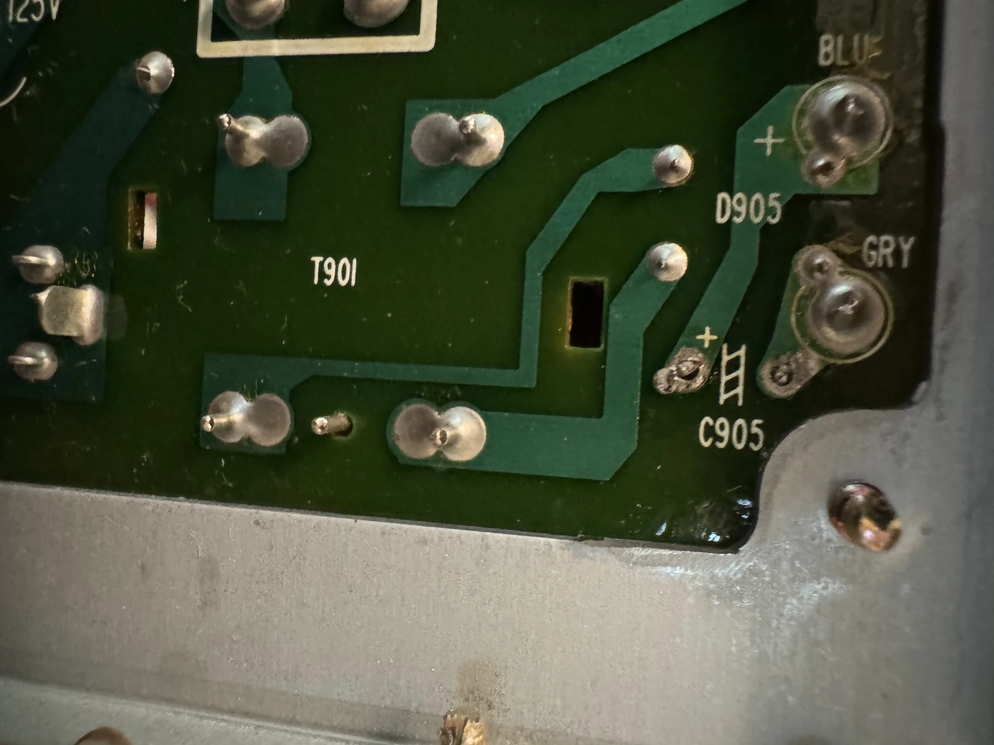
Here are all of the capacitors I removed. These will be thrown away as it is assumed that as they are aging some could be bad.
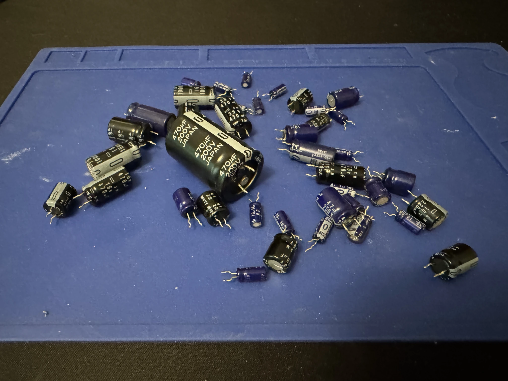
Now with capacitors removed, I finish cleaning the circuit boards to make myself happy.
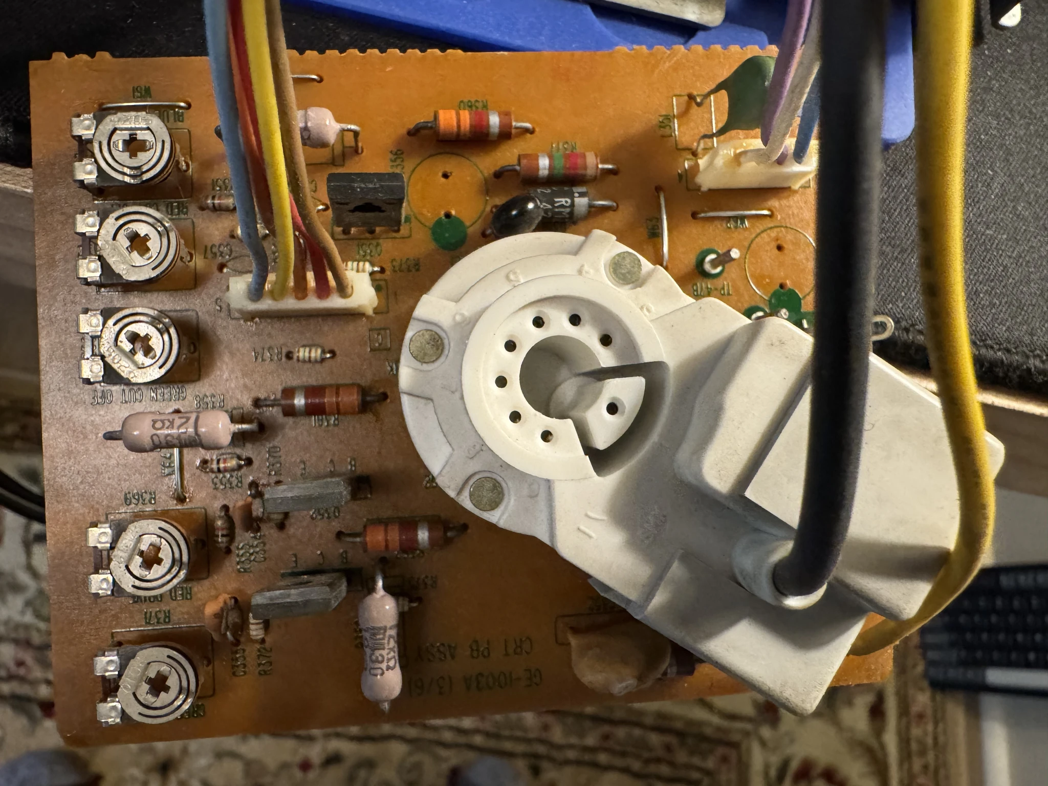
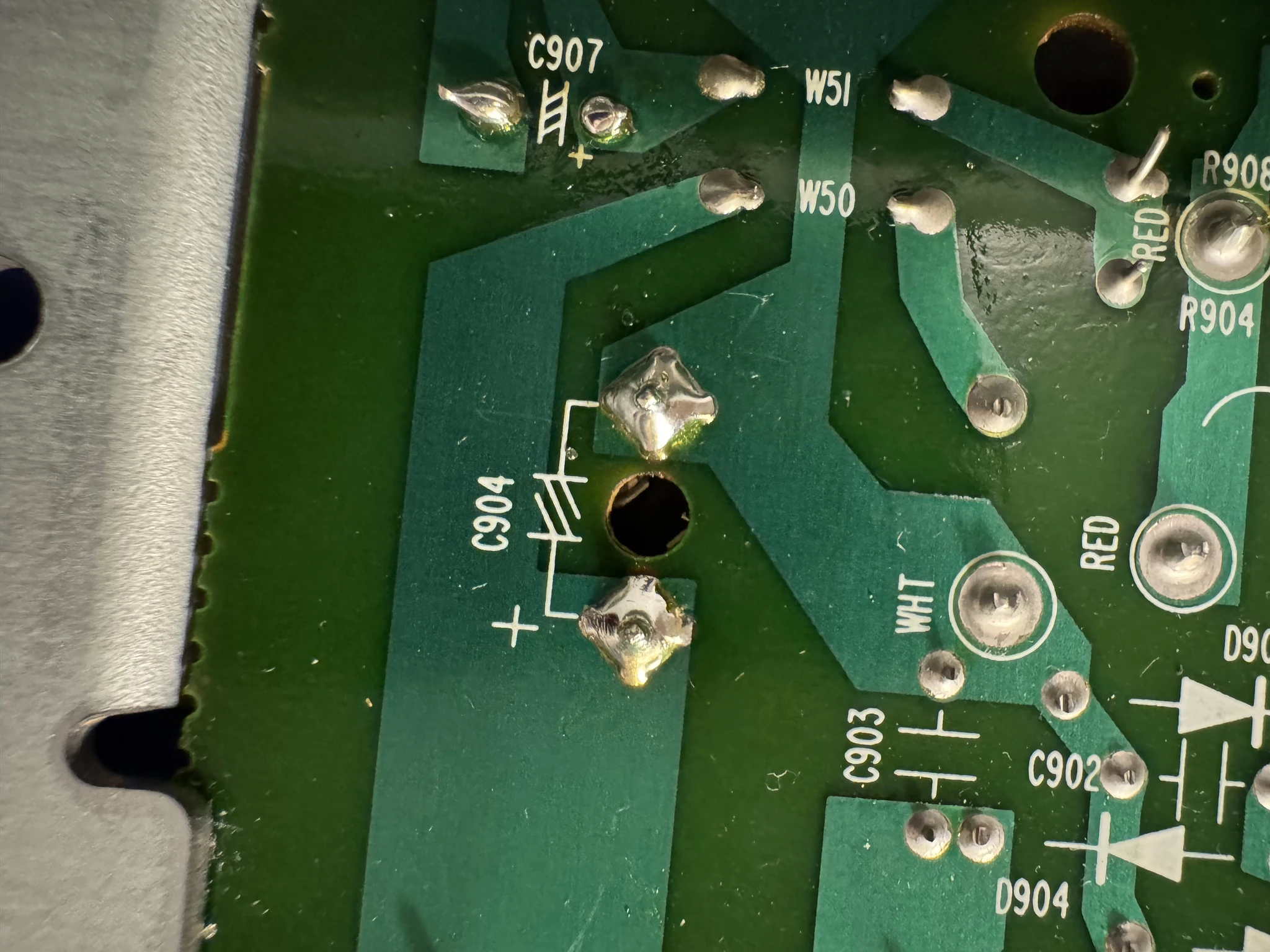
Here I’ve soldered on a couple already, positions C904 and C907. The circuit board has a specific icon for capacitors.
Here I’m soldering in the capacitor at position C541. I poked the longer lead through the positive hole and the shorter lead through the negative hole. I’ve added a little flux goo on the point to be soldered. Flux will help lead the solder to the metal.
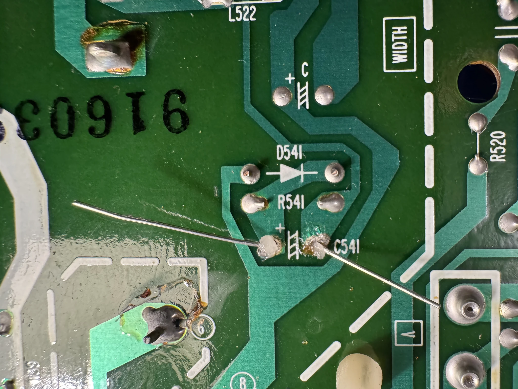
I use the soldering iron to head up the leg and metal on the board. Not pictured, I’ve dabbed some solder onto it from a roll of soldering wire.
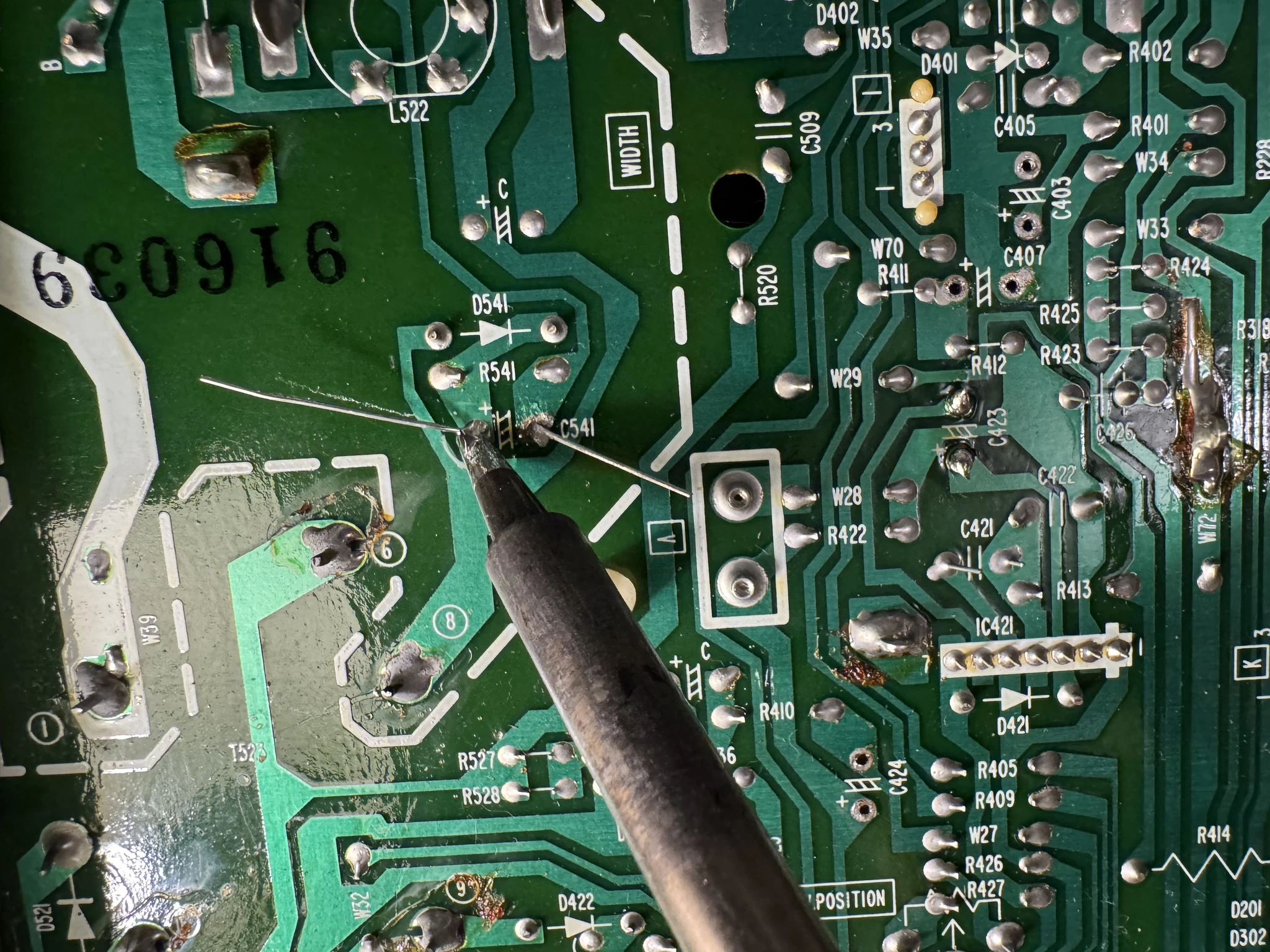
The solder contact looks good so I can cut the legs.
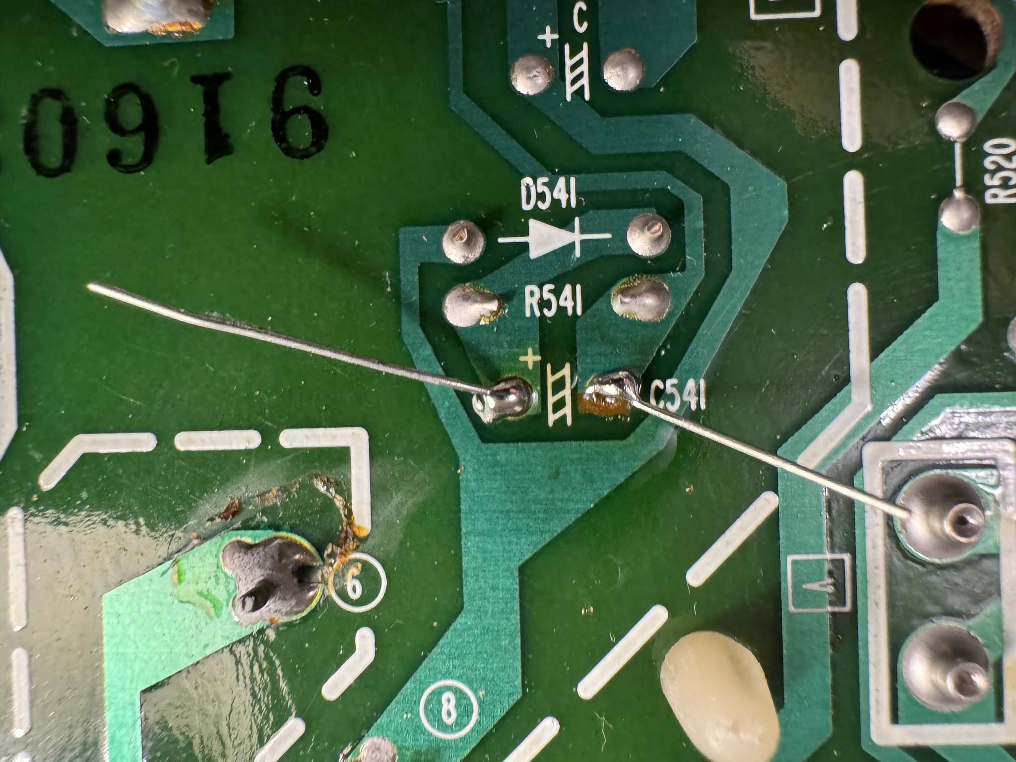
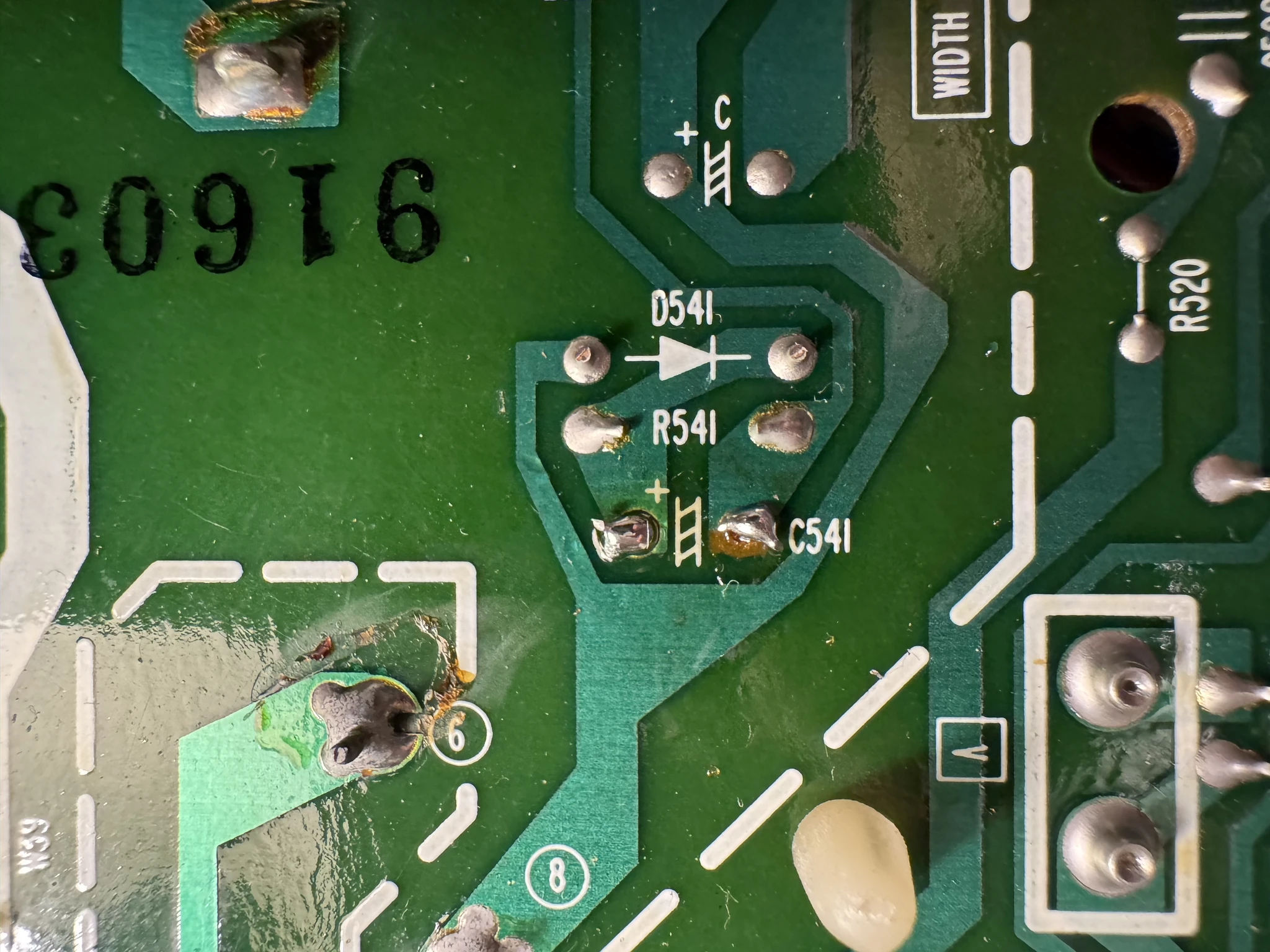
Done with this one. 30+ more to go.
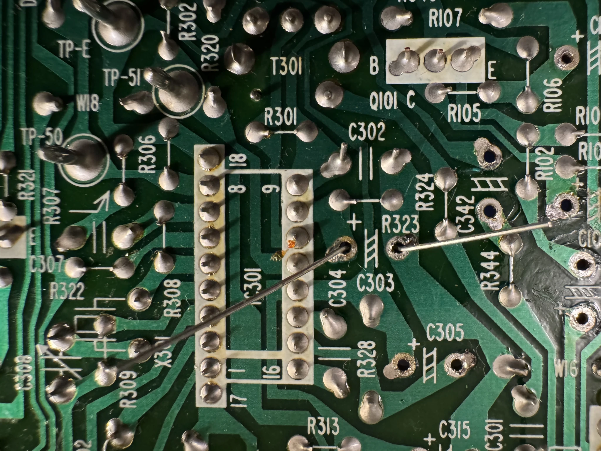
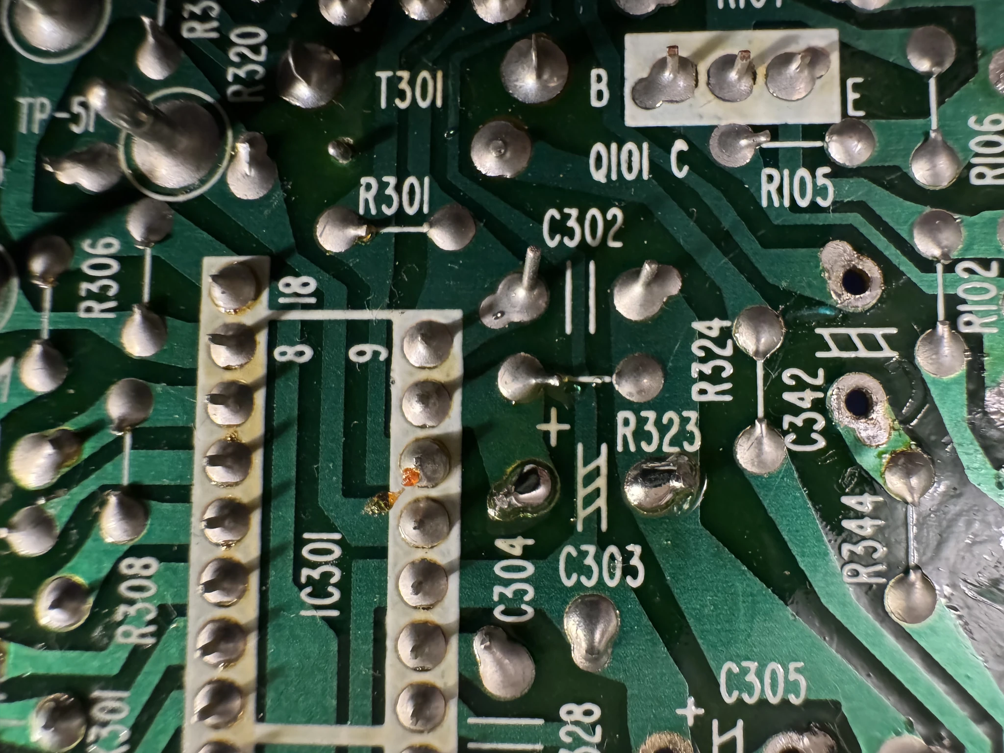
Some pictures of me doing C303…
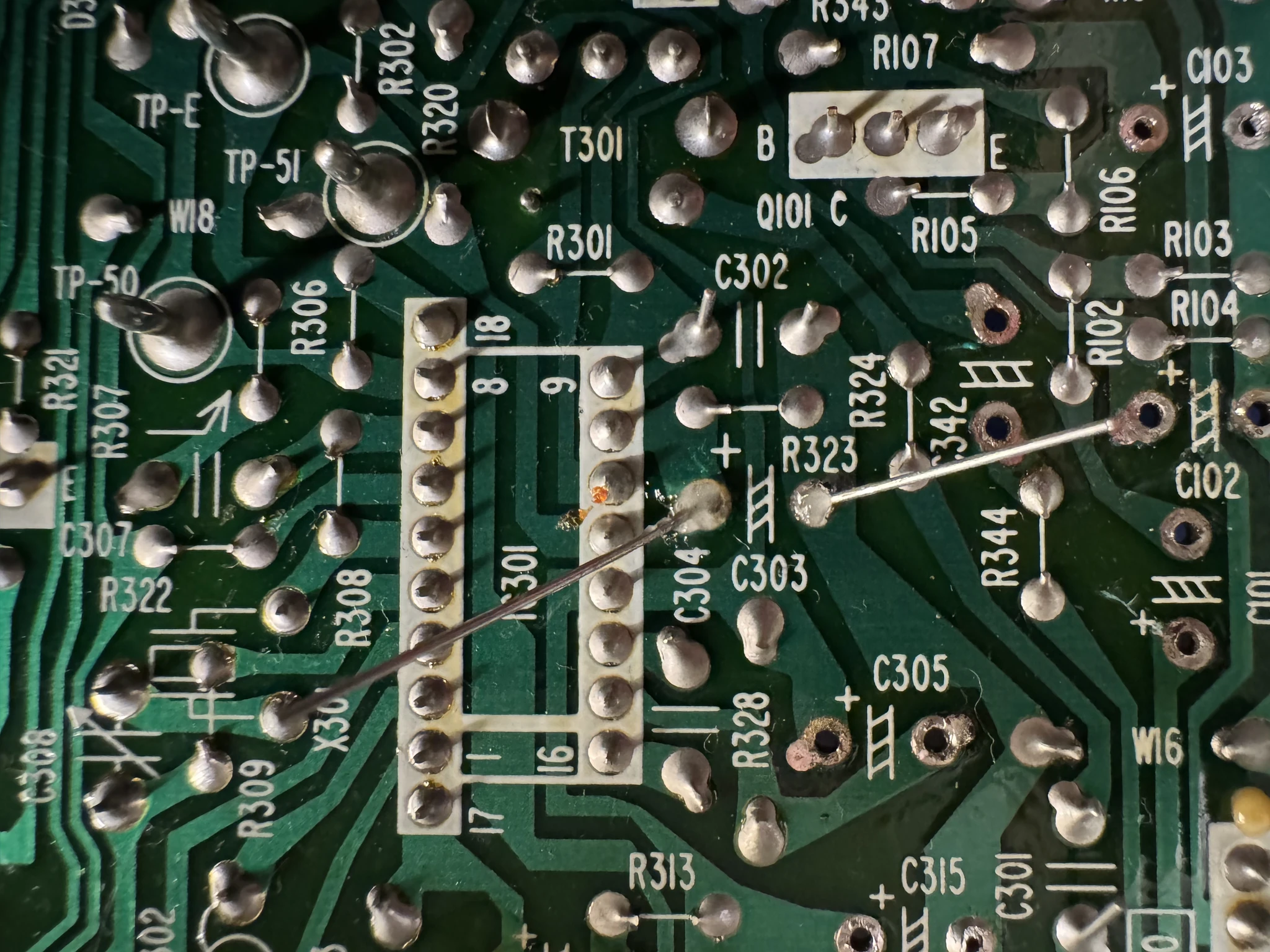
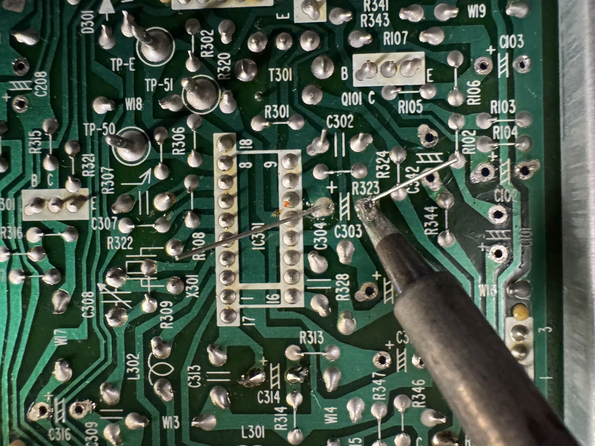
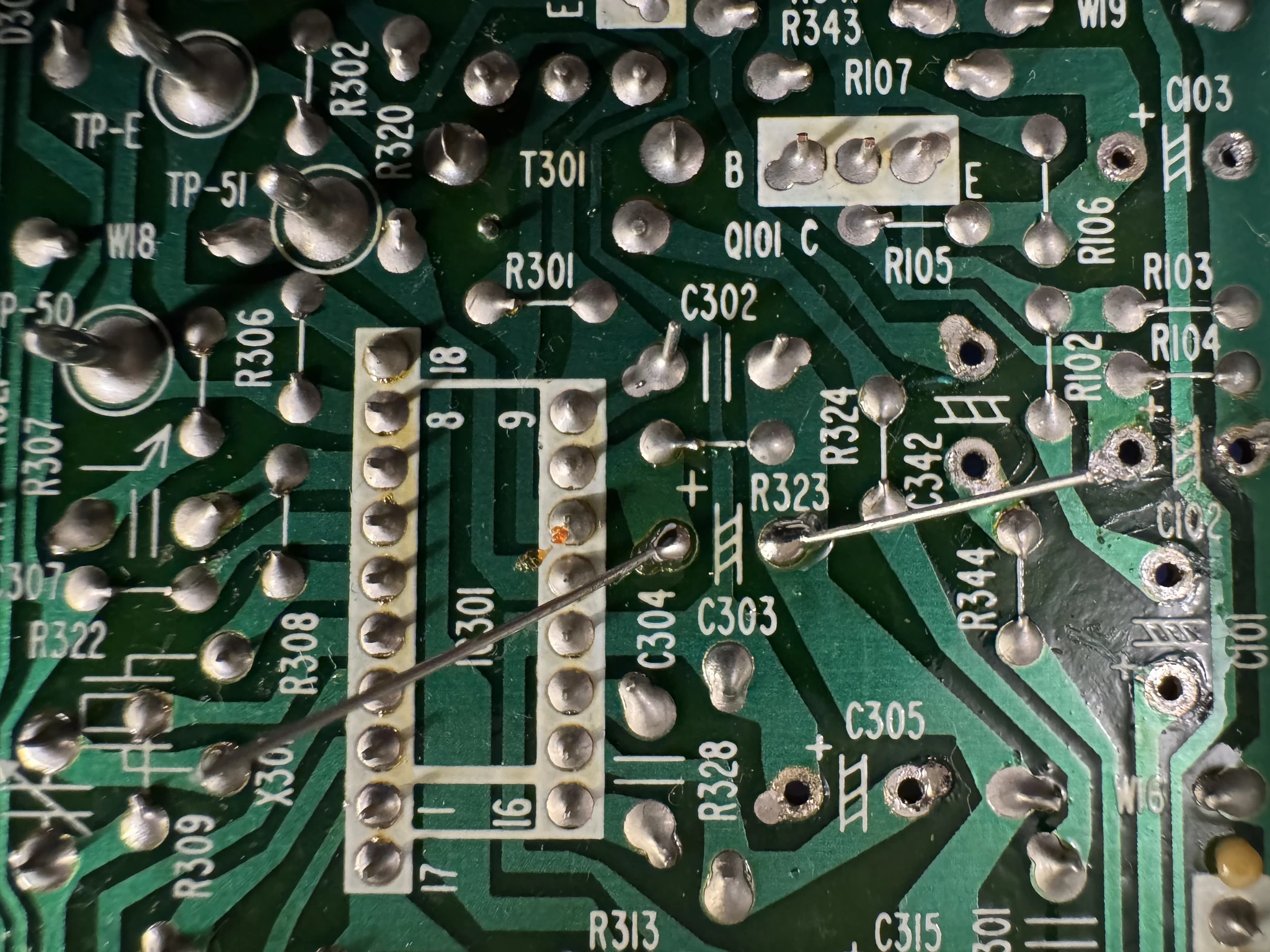
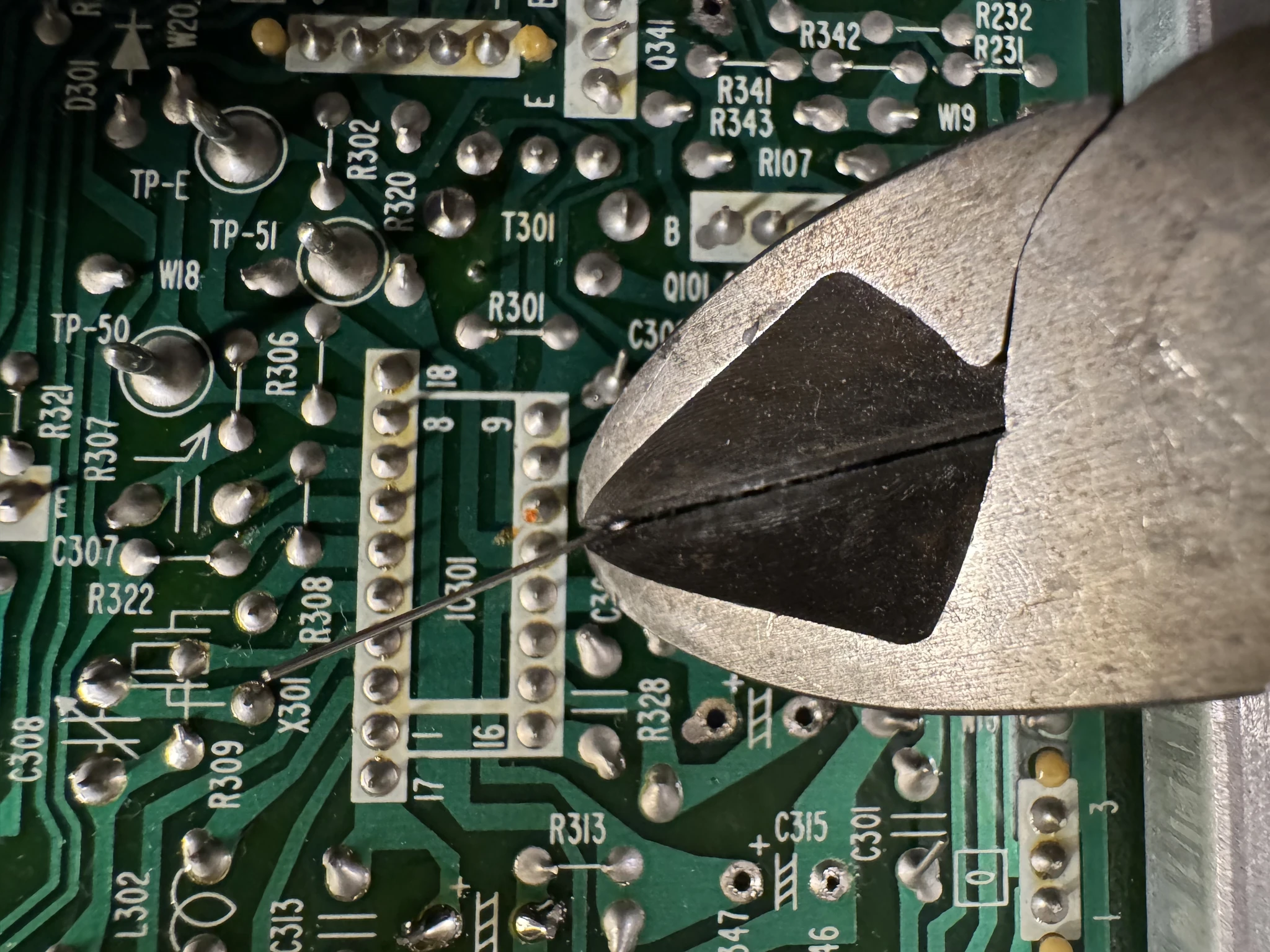
The bottom of the board when I’m done.
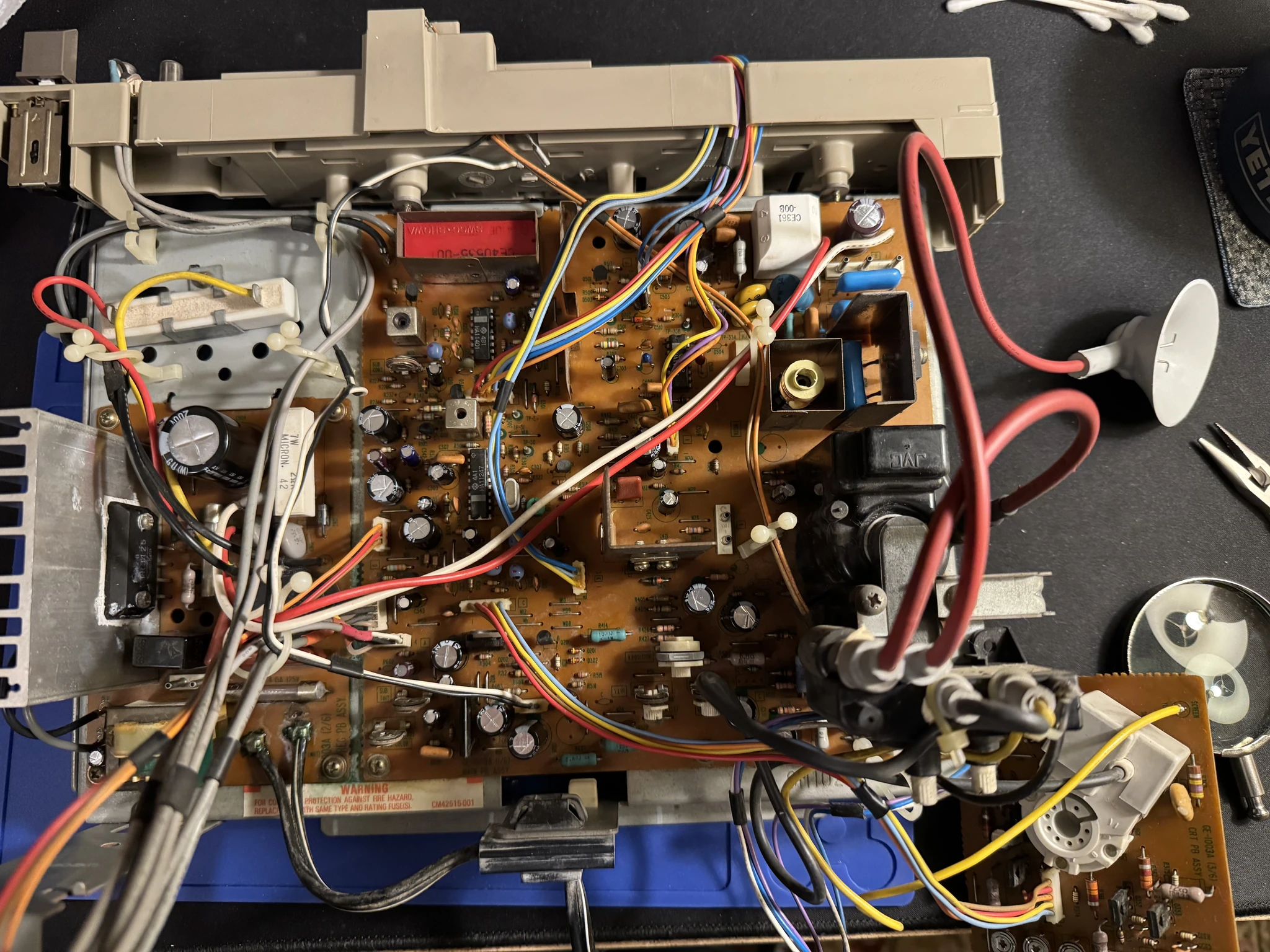
And the top of the board. Looks pretty good.
I reinsert the board into the case.
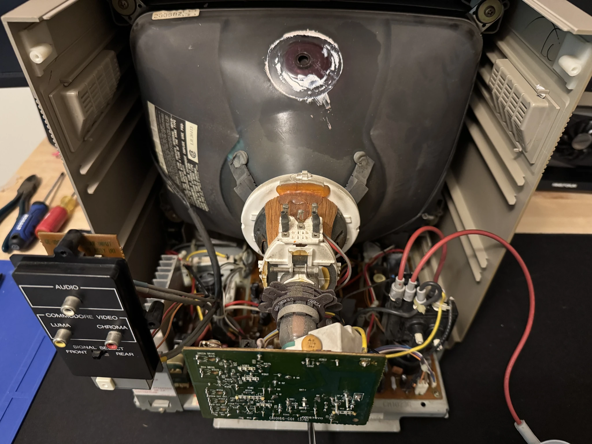
I cleaned up the anode suction cup and add some new silica gel and put the anode cup on the tube.
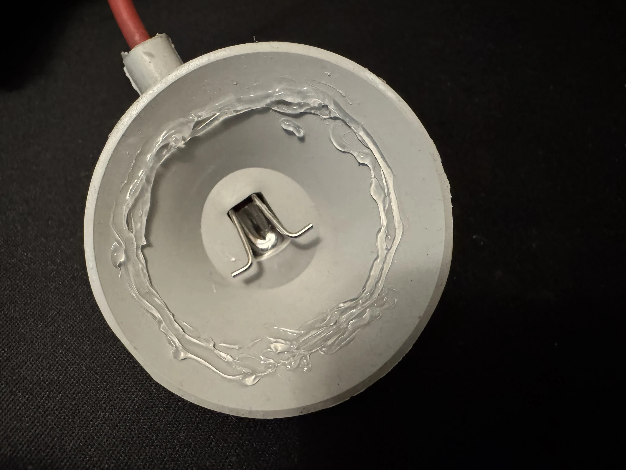
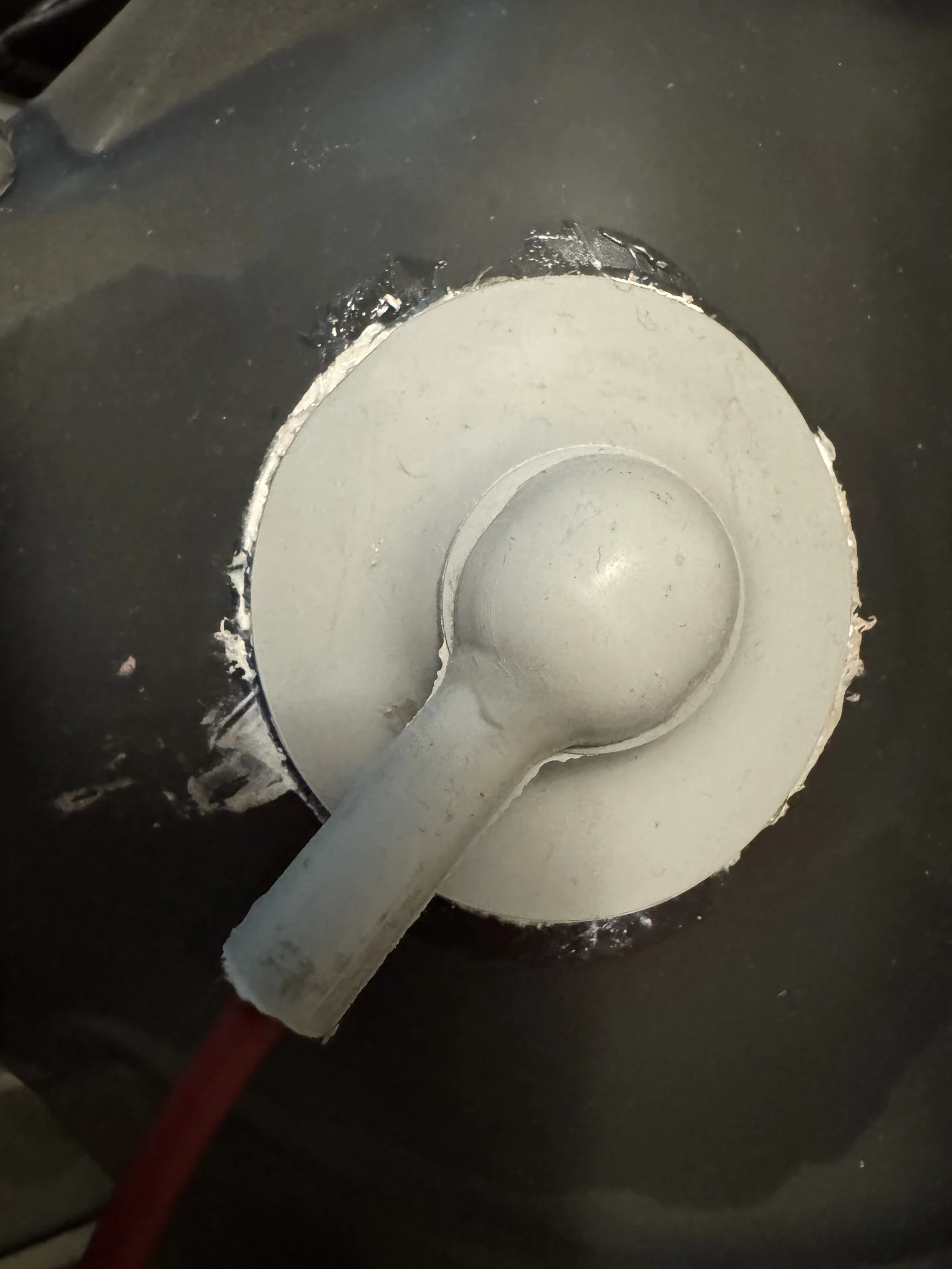
To be honest, I didn’t get this quite right the first time. You have to make sure the anode wire gets hooked into the hole it is mounted on in the CRT. I thought mine was tight but it wasn’t. The behavior was the display was bouncing around and there was a a clicking and hissing noise.
This problem paused progress an extra day. I had to let the CRT leak its charge just in case, then discharge it and trying again. As it turned out, when I attempted to discharge the tube I noticed that the anode wasn’t hooked up correctly at all. When I connected it correctly and put it all back together it worked!
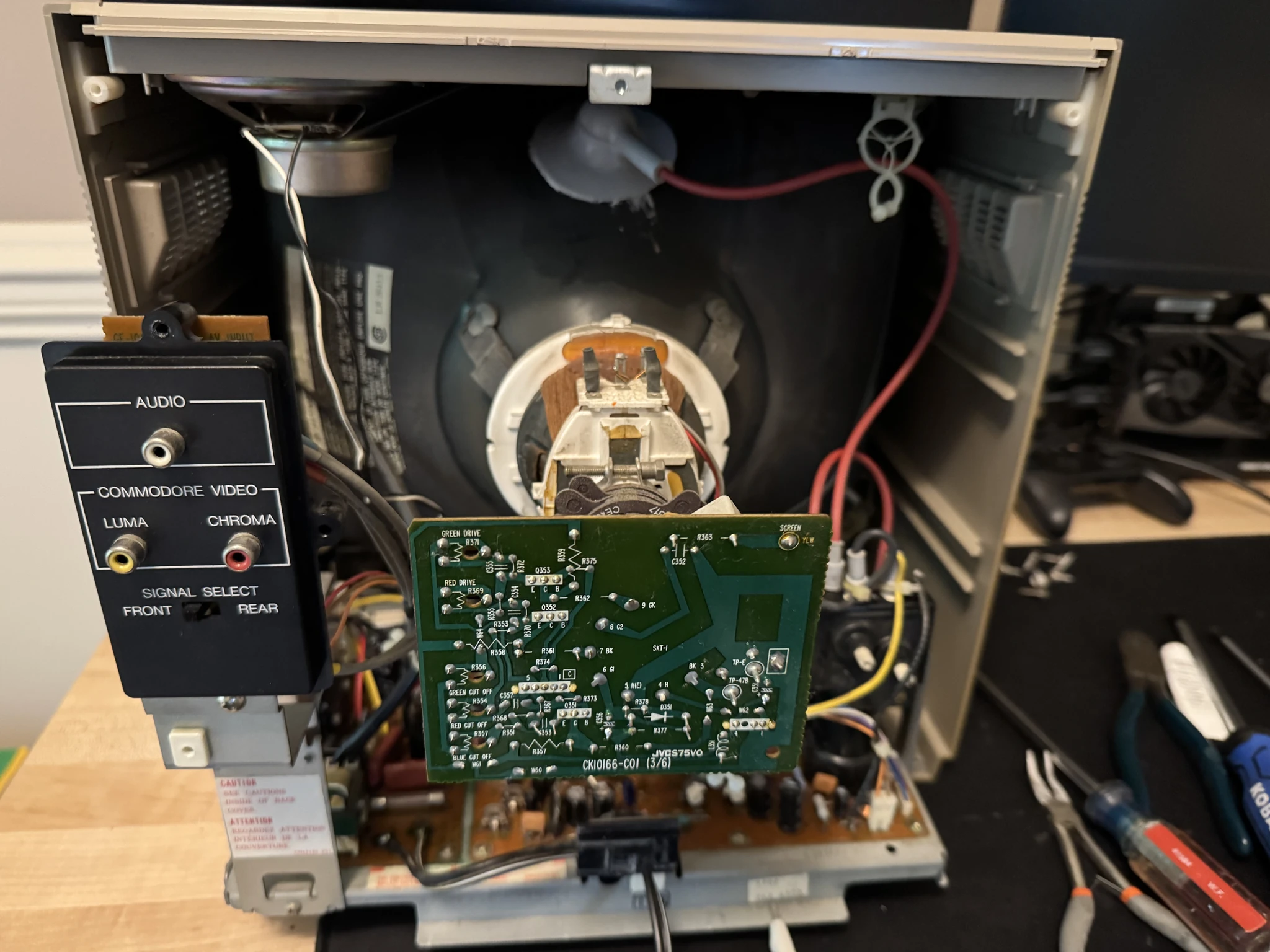
The back is ready to be put back on.
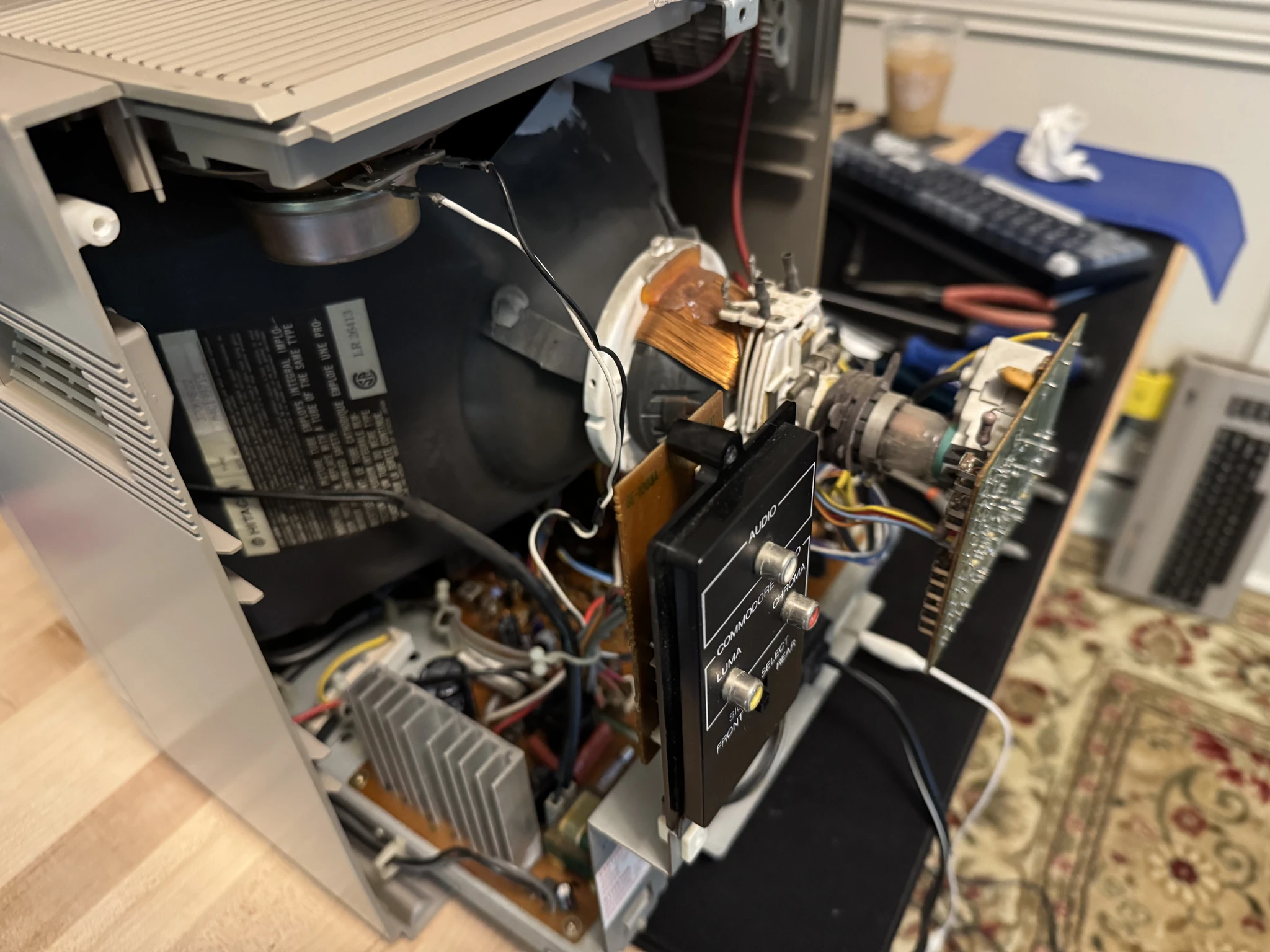
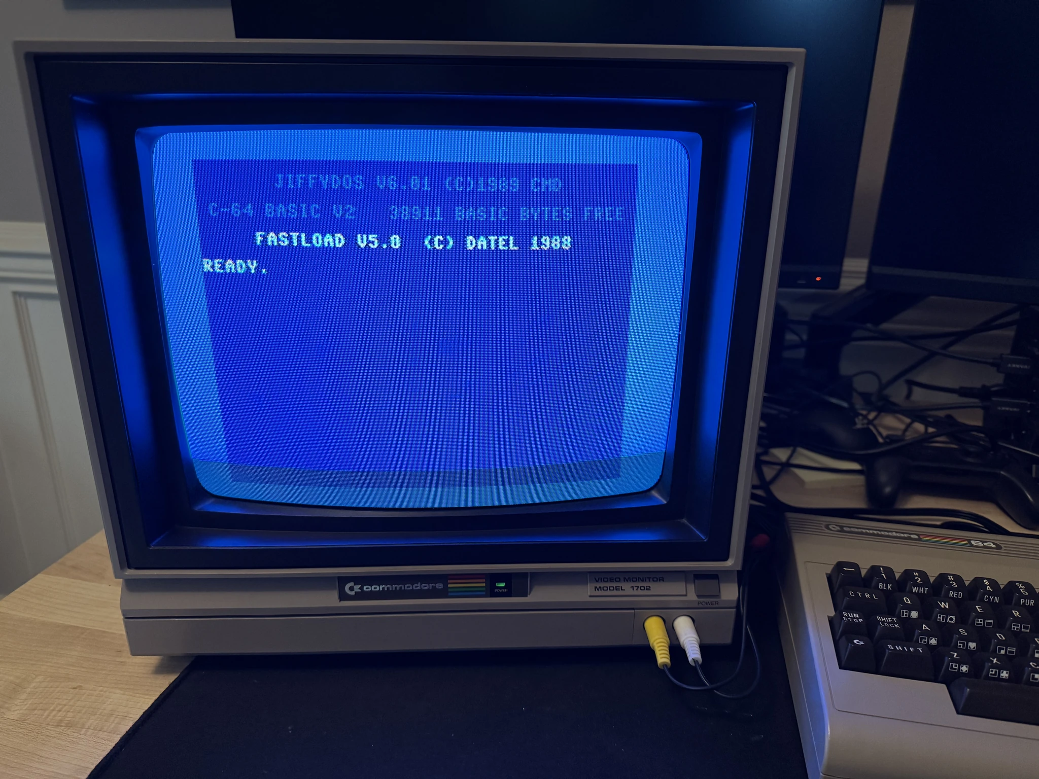
I connect a Commodore 64 computer to the monitor and it works!
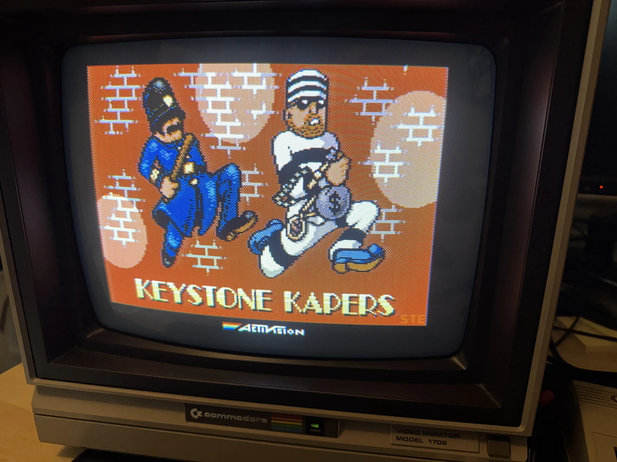
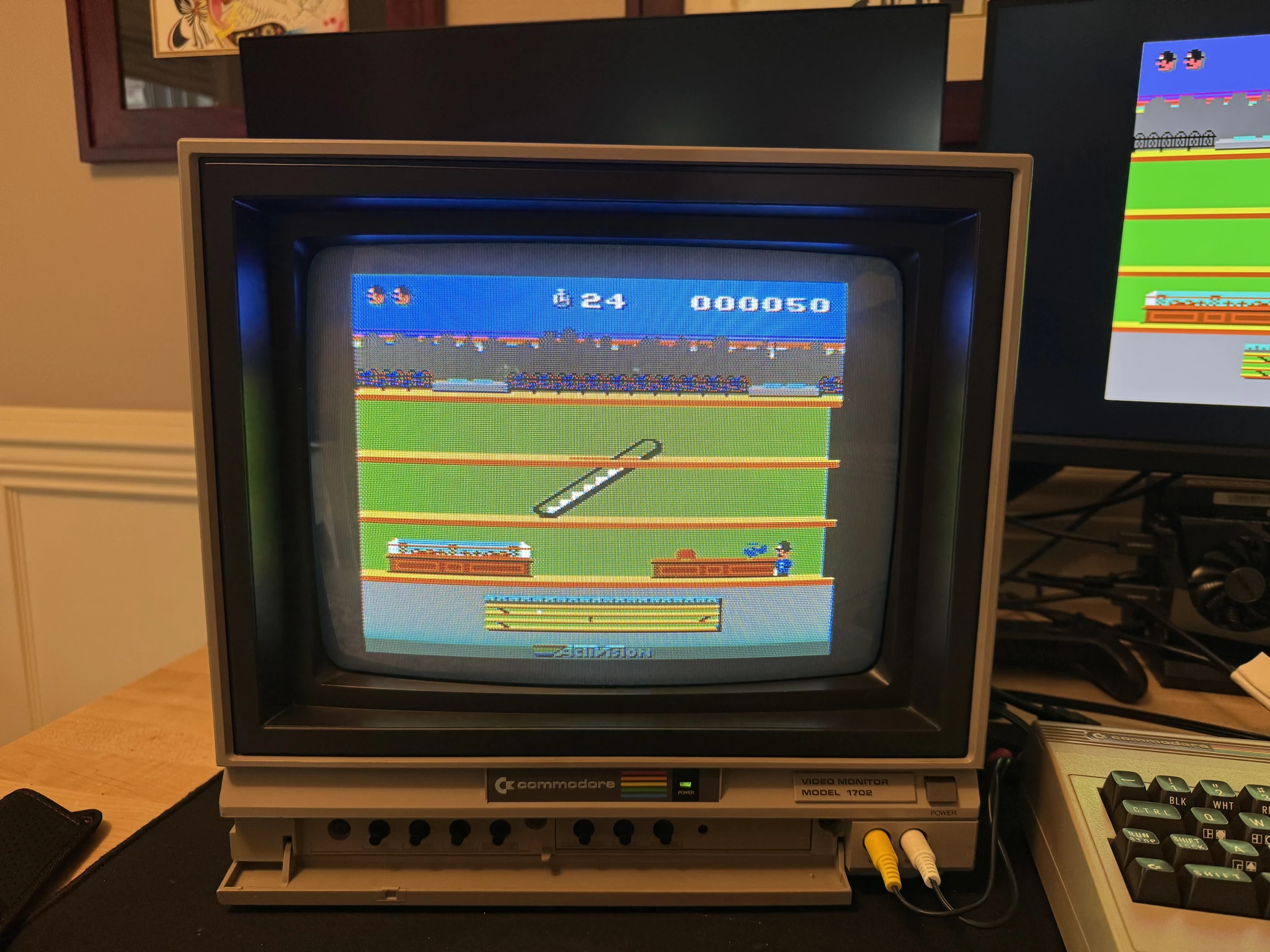
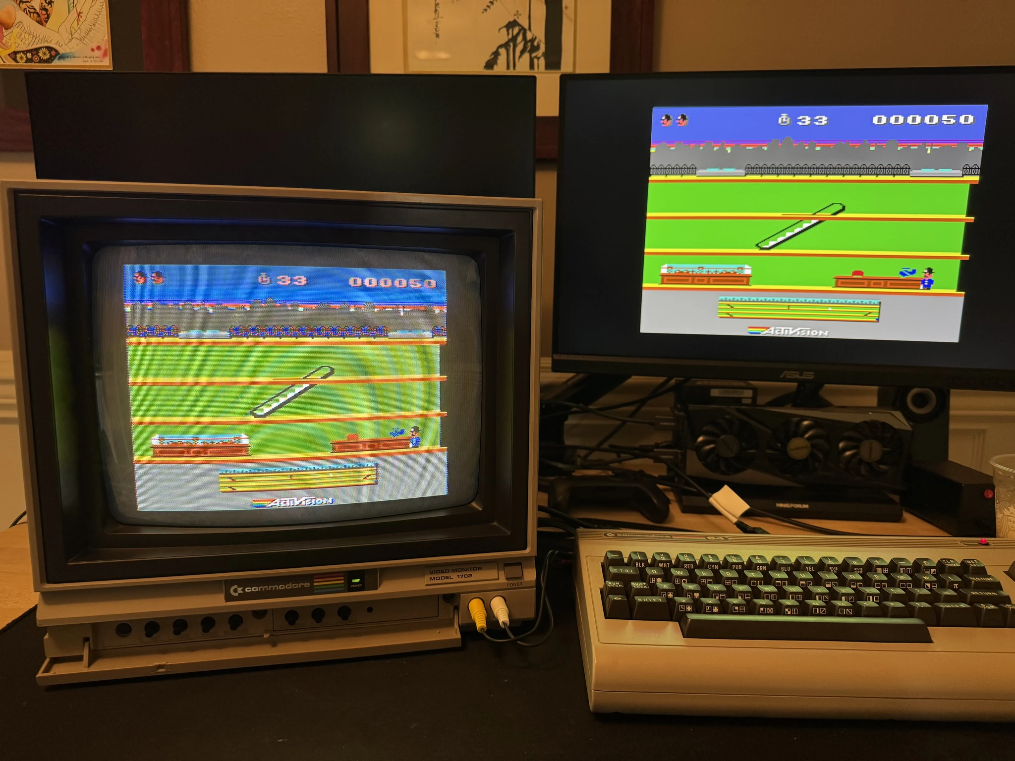
Here is a game shot on the 1702. You can see the nice “woven” effect of individual pixels surrounded by black. Its like each pixel is a small lamp.
On this C64 I’ve installed a Vic II Kawari board which replaces the original Vic II graphics chip. This is the HDMI output on a modern day monitor. Each pixel block is fully filled. I guess its a matter of taste as far as which looks better.
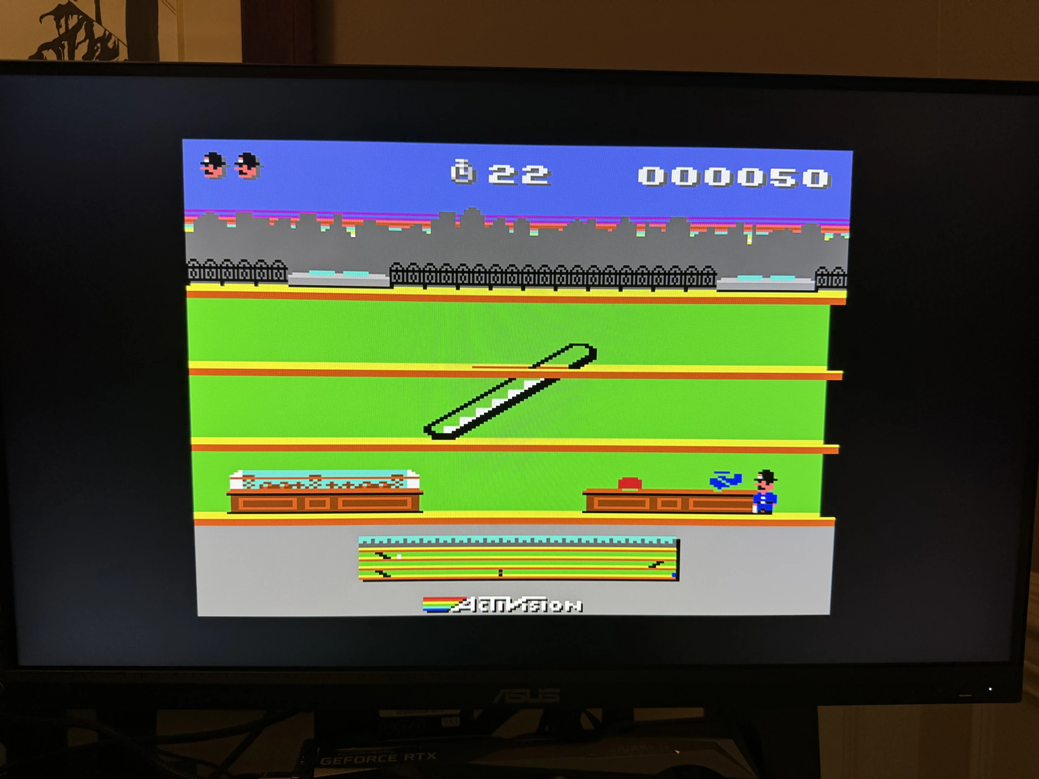
The two screens side by side.
I hook up my Vic20 computer to the 1702 monitor.
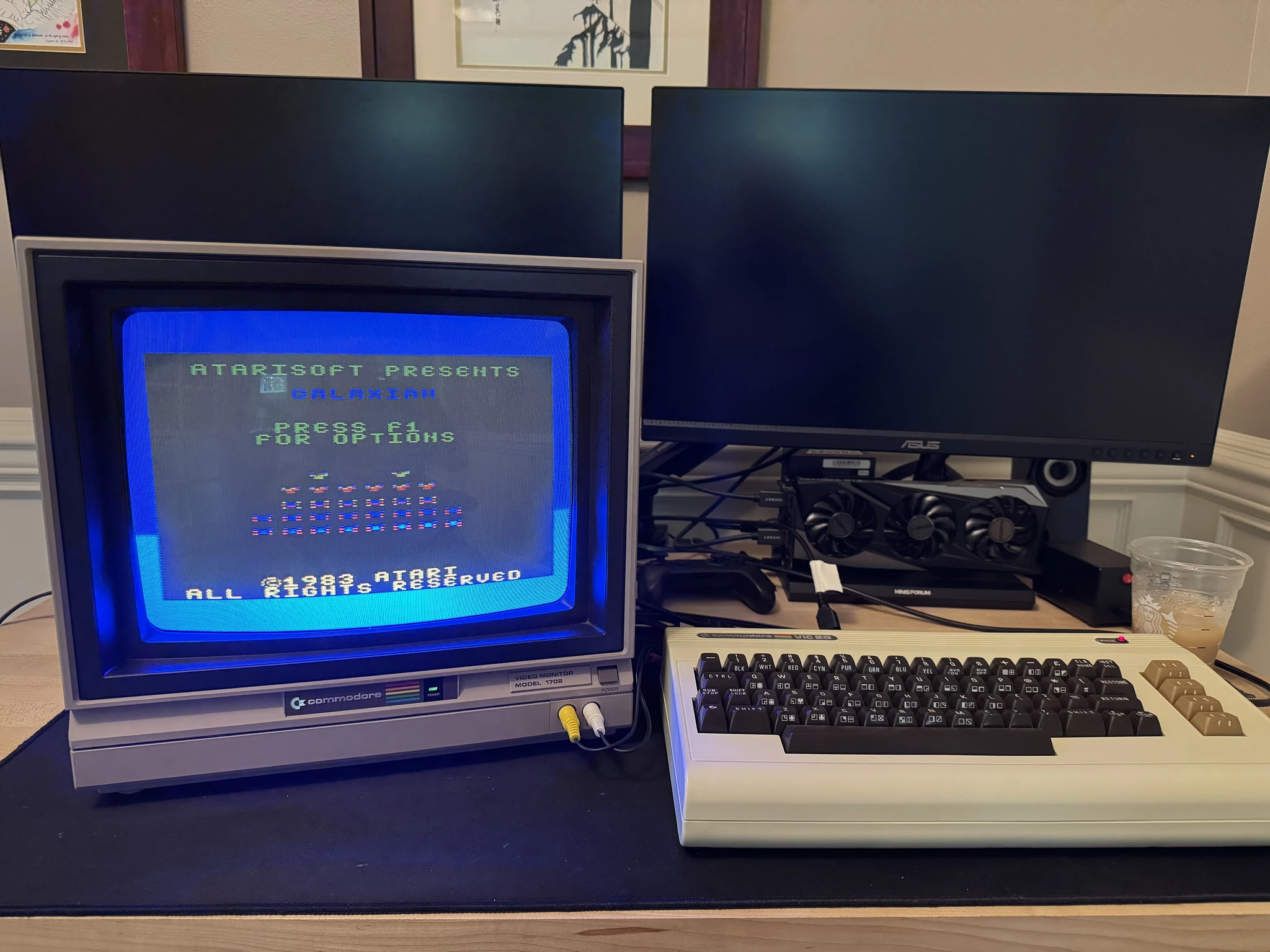
I probably should have turned off the room lights for this picture.
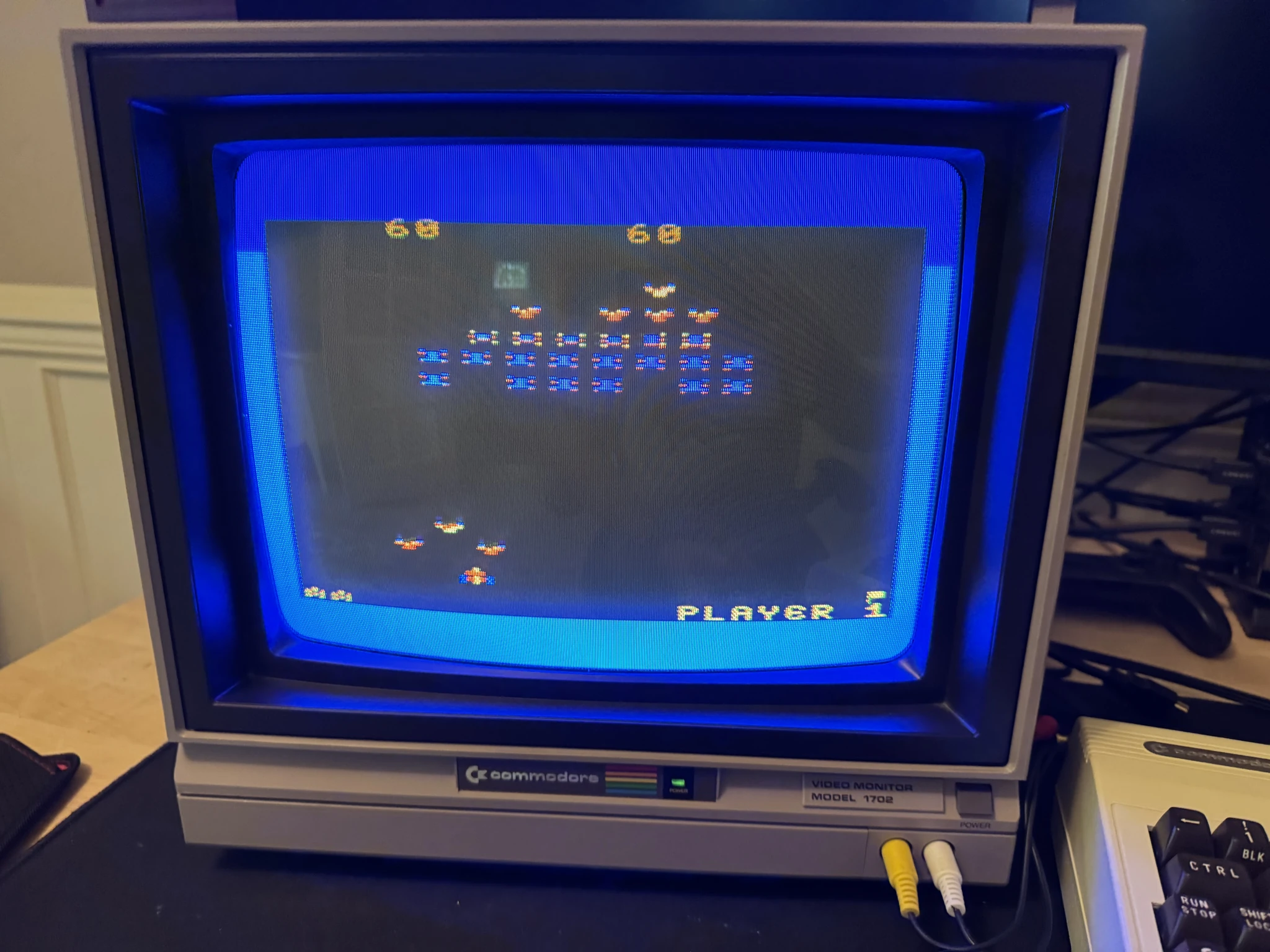
The project was a big success! When I want to share the full retro experience with someone, I can show them what 8 bit computers looked like on the monitors used when these computers were popular. I can also enjoy some retro goodness with this monitor using many of my computers from the 8 bit days.
I’ll post more details about my retro computer collection in future pages on this site.